
Last updated: August 15, 2026
Key Takeaways
- Design for manufacturability (DFM) in sheet metal prevents cracking, distortion and rework by applying bend-radius, flange-length, hole-placement and tolerance rules before release.
- Proper bend radius and material selection, such as 1T for mild steel and 1.5T–3T for stainless or 6061-T6 aluminum, prevent outer-fiber cracking and springback issues.
- Correct flange length, bend relief and hole-to-bend spacing (minimum 2T + R) keep parts from distorting or tearing during press-brake forming.
- Finishing details such as powder-coat clearance, masking of threaded holes and grounding pads, and drainage holes must be defined at the DFM stage to avoid fit and conductivity failures.
- Partner with Fabcon early in the design cycle to align fabrication, finishing and assembly under one roof and cut post-production rework.
Master DFM Rules
DFM rules for sheet metal cluster around a few recurring failure modes. The following sections cover the highest-impact rules, organized by cracking, distortion, hole deformation, tolerance drift and finishing defects. Each rule ties to a specific process stage where it must be applied.
Preventing Cracking with Proper Bend Radius and Material Selection
Outer-fiber cracking occurs when the bend radius is too tight for material thickness and ductility. A 1T inside radius is a safe default for most mild steel and formable aluminum such as 5052 in common gauges, while stainless steel and 6061 aluminum typically require 1.5T or more to reduce cracking risk.
Grain Direction and K-Factor Considerations
Grain direction governs cracking risk on aluminum alloys. Bending 6061-T6 across the grain is safer than bending with the grain. The alloy has low ductility in T6 temper, so radii of 3T to 6T reduce outer-fiber cracking. K-factor selection should match actual material and tooling conditions, not a generic 0.33 default. This matters for stainless and high-strength alloys where springback is pronounced.
Avoiding Distortion with Correct Flange Length and Bend Relief
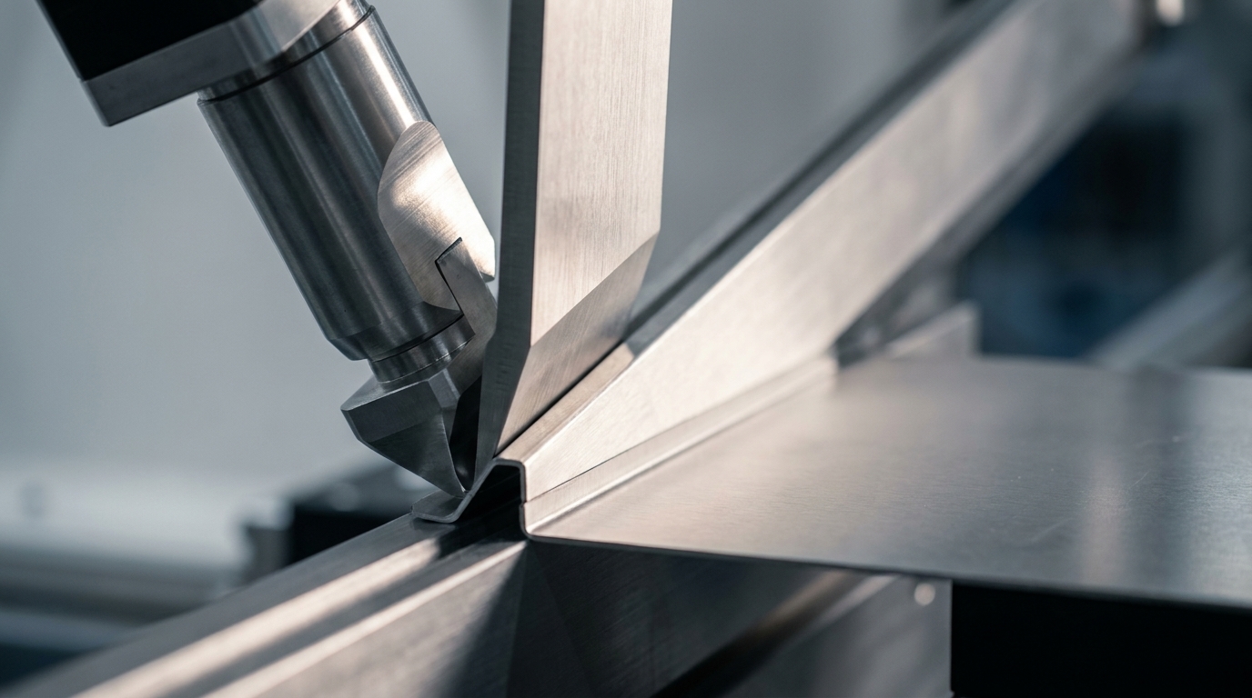
Correct flange length keeps parts stable in the press-brake V-die and prevents angle drift. Minimum flange length for press-brake bending depends on die geometry, typically about 0.7V, rather than a fixed 4T multiplier that can create distortion and scrap.
Bend Relief and Sequencing
Bend relief prevents corner tearing where two flanges intersect. Relief width should equal at least T and depth should clear the bend radius plus T. Corner relief slots serve the same function on box-form parts and reduce stress at intersections. Sequencing bends from inside features outward limits springback accumulation and cuts the number of repositions required at the brake.
Eliminating Tool Access and Deformation Issues Around Holes and Slots
Holes placed inside the bend deformation zone tend to oval, teardrop or tear during forming. The minimum hole-to-bend distance is 2T + R for holes under about 1 inch in diameter and 2.5T + R for larger holes or slots, where T is material thickness and R is inside bend radius.
Cut Method and Edge Quality
Cut-method selection between punching and laser cutting affects edge quality and fatigue performance. The heat-affected zone from laser cutting hardens and embrittles the edge, which raises crack-initiation risk under cyclic loading. For fatigue-sensitive applications, punching or post-laser edge treatment should be specified on the drawing.
Dimensioning, Tolerances and Flat-Pattern Practices for Bent Parts
Tolerances on sheet metal parts should match the forming process, not machining conventions. Precision sheet metal fabricators hold laser-cut holes and edges within standard industry tolerances, formed dimensions and flange lengths within standard industry tolerances, and bend angles within about one degree.
Tight tolerances belong only on assembly-critical features. ISO 2768 fits non-critical dimensions and avoids unnecessary precision-machining cost. Grouping tolerances by feature type reduces fabrication cost on tolerance-dense designs.
Flat-pattern datums should reflect how the part is fixtured and inspected, not how it was modeled in CAD. Position tolerances on same-plane hole patterns and profile tolerances on formed contours are high-value GD&T tools in sheet metal. Datums should follow fixturing and use so bend variation does not distort measurements. Critical-to-fit dimensions should be flagged on the drawing so inspection effort targets features that affect fit, safety or sealing.
Integrating Finishing and Electromechanical Assembly into DFM
Finishing and assembly decisions made late in the design cycle often trigger rework. Addressing them at the DFM stage prevents the most common post-production failures.
Powder Coating
Coating buildup from powder coating adds thickness to every exposed surface and changes fit. Designers should add clearance on mating surfaces for tab-and-slot fits, door-to-frame gaps, hinge knuckle clearance, inserted hardware, mounting rails, removable panels and gasket grooves so parts that fit in bare metal still move freely after coating.
Sharp edges cause thinner powder coating at corners because surface tension pulls coating away during cure. Designers should specify a minimum edge radius through deburring, tumbling or drawing callouts to prevent premature coating failure.
Powder coating is non-conductive and adds thickness, so any feature that needs electrical contact, mechanical engagement or precise dimensional control must be masked or left uncoated. This includes threaded holes, grounding pads, gasket lands, EMI contact areas, weld nuts and precision datum pads.
Enclosed or semi-enclosed sheet metal sections need drainage holes sized and placed at the lowest point in coating orientation. These holes prevent trapped pretreatment chemicals, rinse water or air that cause staining, blistering and outgassing defects.
Weld Access and Hardware Insertion
Welding in sheet metal assemblies should be limited to only where necessary, with preference for lower-effort methods such as clinch nuts or folded one-piece solutions to reduce part count and labor. When welds cannot be avoided, two DFM rules apply. Weld joints must be accessible from the main assembly opening to allow proper tooling access. Weld quality must limit porosity that can cause outgassing pinholes under powder coating.
Grounding and Gasket Considerations
The non-conductive coating discussed above requires dedicated masked grounding points to maintain electrical grounding. Gasket compression flanges must be dimensioned for coating buildup so the gasket reaches the specified compression ratio after finishing.
Design Release Checklist
The following checklist converts the rules above into a procurement-ready format. Engineering and NPI teams should verify each item before releasing drawings to fabrication.
Bend Radius and Material
- Inside bend radius is ≥ 1T for mild steel and stainless; ≥ 2T–3T for 6061-T6 aluminum on thin gauges
- Grain direction is noted on the drawing for aluminum alloys
- 6061-T6 bends are oriented across the grain where possible
- K-factor reflects actual material and tooling, not a generic default
- Material temper is specified; O or T4 temper noted where tighter radii are required on 6061
Flange Length and Bend Relief
- All flanges are ≥ 4T + inside bend radius for air bending
- Folding-machine flanges are ≥ 2T + inside bend radius where applicable
- Bend relief slots are present at all corners where flanges intersect
- Relief width ≥ T; relief depth ≥ R + T
- Bend sequence is defined to minimize springback accumulation
Holes and Slots
- Punched hole diameter ≥ 1T; laser-cut holes sized per gauge capability
- Hole-to-edge distance ≥ 2T for punched holes; ≥ 1T for laser-cut holes
- Hole-to-bend distance ≥ 2T + R for holes under 1 in diameter
- Hole-to-bend distance ≥ 2.5T + R for holes ≥ 1 in diameter or slots
- Hole-to-hole spacing ≥ 2T solid material between adjacent holes
- Threaded and extruded hole edge clearance ≥ 2T–3T
- Relief cuts specified for holes that cannot be repositioned outside the deformation zone
- Cut method (punch vs. laser) specified for fatigue-sensitive hole edges
Tolerances and Dimensioning
- Tight tolerances applied only to assembly-critical features
- ISO 2768 called out for non-critical dimensions
- Datums reflect fixturing and inspection method, not CAD origin
- Critical-to-fit dimensions flagged explicitly on the drawing
- Tolerance stack-up reviewed across multi-bend assemblies
- Slotted holes or self-locating tabs specified where stack-up risk is identified
- Secondary machining operations identified and justified by functional requirement
Finishing
- Mating surface clearances account for powder-coat buildup on both surfaces
- Minimum edge radius of 0.5 mm specified via deburring or drawing callout
- Threaded holes, grounding pads, gasket lands and EMI contact areas flagged for masking
- Drainage holes specified on enclosed or semi-enclosed sections
- Critical dimensions marked “required after coating” on the drawing
- Weld quality meets ISO 5817 level B; spatter removal specified before coating
- Hanging points for racking specified in non-critical, non-visible areas
- Recessed features have internal corner radii ≥ 3–5 mm to reduce Faraday cage effect
Assembly and Hardware
- PEM studs and standoffs installed before powder coating
- All fasteners accessible with standard tools from the main assembly opening
- Cable routing and component mounting points defined at the design stage
- Grounding points specified near power supply entry with lock washers and nuts
- Gasket compression flanges dimensioned to account for coating buildup
- BOM, work instructions and test procedures released before electromechanical assembly begins
- Self-locating tabs and slots incorporated to reduce fastener count and misalignment risk
- Off-the-shelf hardware used wherever possible to simplify NPI and production ramp
Prototype-to-Production Alignment
- Prototype produced using the same flat patterns, bend sequences and finishing notes as production
- First article inspection completed with dimensional report and material cert before production release
- Pilot run verifies cycle time, fixture performance, finish quality, hardware installation and rework rate
- Documented process data and controls are identical for prototype and mid-volume production
Frequently Asked Questions
What is the most common DFM mistake that causes cracking in sheet metal parts?
The most common cause of cracking is an inside bend radius that is too tight for the material and temper. For 6061-T6 aluminum, the 3T minimum radius and cross-grain orientation discussed earlier become critical. Bending with the grain or using tighter radii often causes cracking. Specifying material-appropriate radii and noting grain direction for aluminum alloys on the drawing prevents this issue before the part reaches the press brake.
How does powder coating affect part fit, and when should it be addressed in the design process?
Powder coating adds measurable thickness to every exposed surface. The coating buildup discussed earlier affects any close-tolerance feature. A slide fit or tab-and-slot joint that clears in bare metal can bind after coating if the designer did not account for buildup on both mating surfaces, so the DFM stage must address clearances before release. These clearances and masking requirements should be defined at the DFM stage, and marking critical dimensions as “required after coating” on the drawing ensures the fabricator and finisher inspect to the correct condition.
Why do parts that pass prototype inspection fail to hold tolerances in mid-volume production?
Prototype parts are often built by senior operators who make manual adjustments, use improvised fixtures and accept cosmetic rework. When the same drawing moves to a production line without documented processes, dedicated fixtures and formal inspection records, those informal adjustments disappear and variation increases. Producing prototypes with the same flat patterns, bend sequences, weld fixtures and finishing notes that will govern production, then completing a first article inspection before volume release, closes this gap. Suppliers that run prototype and production through the same documented controls maintain consistent results.
When should punching be specified instead of laser cutting for holes in sheet metal?
Laser cutting is faster and more flexible for complex contours, but the heat-affected zone it creates hardens and embrittles the edge. For parts subject to cyclic loading or fatigue, punched holes or post-laser edge treatment should be specified on the drawing. For high-strength steel grades, the difference in edge ductility between punched and laser-cut holes can affect hole-expansion performance. Cut method should follow the part’s in-service loading and material grade, not machine availability alone.
How does Fabcon’s integrated model reduce DFM-related rework compared to using multiple vendors?
When fabrication, finishing and assembly are split across separate vendors, DFM issues discovered at the finishing or assembly stage often require costly rework. Fabcon’s integrated model keeps these processes under one roof, which allows early detection and correction of design issues before they reach production.