
Last updated: August 15, 2026
Key Takeaways for Sheet Metal DFM
- Sheet metal DFM turns material and machine limits into clear geometry choices at the CAD stage for accurate, repeatable and economical production.
- Early DFM collaboration with a vertically integrated fabricator catches violations that cause rework, quoting delays and cost overruns before production begins.
- Core design rules address hole-to-bend distance, minimum flange length, bend relief geometry, inside bend radius, K-factor, press-brake access, tolerance strategy, finishing integration and hardware placement.
- A systematic 30-item pre-release checklist across geometry, cut features, manufacturing, assembly, tolerance and cost prevents first-article failures and unbudgeted engineering changes.
- Early collaboration with a vertically integrated U.S. fabricator that reviews geometry, tolerances and finishing requirements before production begins is the most reliable way to move from prototype to mid-volume production without rework, vendor complexity or schedule risk. Get a quote and start a DFM review with Fabcon’s engineering team.
Rule 1: Protect Hole-to-Bend Distance
Holes placed too close to a bend line distort during forming. The material around the hole stretches into the bend zone, which turns circular holes oval or cracks the edge.
A minimum hole-to-bend distance measured from the bend tangent line prevents this distortion. Holes placed closer than this minimum risk ovaling, tearing or shifting position during forming.
Holes too close to bend lines rank among the most common press brake design mistakes. Fabcon’s DFM review flags these issues at the drawing stage before tooling is cut.
Rule 2: Maintain Minimum Flange Length
Short flanges do not seat properly on press brake tooling. The part can slip, rotate or drop into the die opening, which produces inconsistent bend angles and edge distortion.
A defined minimum flange length allows stable engagement with press brake tooling. Flanges shorter than this minimum create inconsistent angles, edge distortion or slippage.
A flange below the tooling minimum can cause part rotation, inconsistent bend angles, edge marking or punch-die interference. When tooling is unknown at the design stage, a conservative formula provides a safe starting point until the production die is confirmed.
Rule 3: Use Effective Bend Relief Geometry
Intersecting bends without relief cause material to bunch at the corner. That bunching creates an uncontrolled bulge that shifts adjacent feature positions and harms dimensional accuracy.
Correct bend relief cuts prevent tearing and control material flow at intersecting bends. Relief width should be at least equal to material thickness, and relief depth should be at least equal to bend radius plus material thickness.
Rule 4: Match Inside Bend Radius to Material Limits
Minimum inside bend radius depends on material, temper and grain direction. A radius tighter than the material allows causes cracking at the outer fiber of the bend.
Published minimums vary by alloy and temper. Mild steel, stainless steel and aluminum require different radii, and some tempers need significantly larger radii because reduced ductility limits formability. In those cases, forming in a different temper followed by aging often supports tight bends.
Grain direction also affects cracking risk. Bending parallel to the grain increases cracking, so bends oriented perpendicular to the rolling direction are preferred. Laser-cut edges create a hardened heat-affected zone that can crack first on thin gauges with tight radii, so deburring before bending helps protect those edges.
Rule 5: Validate K-Factor for Flat Patterns
K-factor controls flat-pattern length. An incorrect K-factor produces parts that run consistently long or short after bending, which drives engineering changes and scrapped first articles.
Published K-factors serve as starting points, not final values. CAD defaults should be replaced with measured shop values, and each shop benefits from internal bend tables tuned to its equipment and tooling. Typical K-factor ranges for air bending vary by material type.
A practical method confirms K-factor on production equipment. Cut a test strip of known flat length, bend it 90 degrees on the actual press brake and tooling, measure the finished outside legs and back-calculate the bend allowance to solve for K. Fabcon’s engineering team validates K-factor against production equipment before releasing flat patterns to the floor.
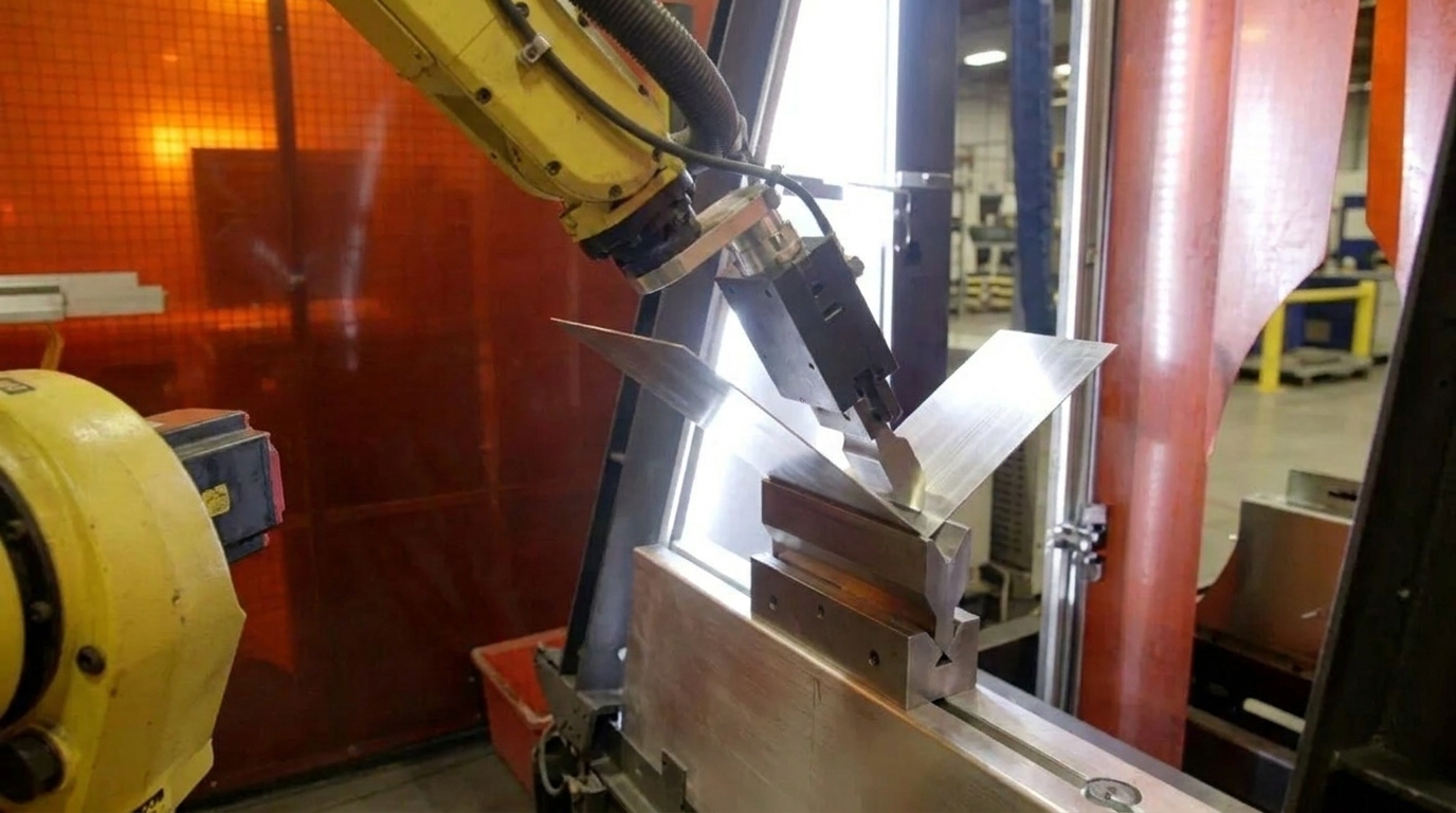
Rule 6: Plan for Press-Brake Access
Inconsistent bend orientations force multiple tool setups. Each added setup increases cycle time and raises the chance of angular error between bends.
Deep flanges or tall walls can also block the punch from reaching the bend line. That blockage can require special offset tooling or redesign.
Aligning bends in the same direction where possible reduces setup changes. Designing parts so the punch has clear access to every bend line avoids special tooling, and grouping required alternate orientations keeps changeovers limited and angles consistent within each setup.
Rule 7: Build a Practical Tolerance Strategy
Unrealistic tolerances inflate cost and extend lead times. Tight limits demand extra fixturing, secondary operations or added inspection, which all increase price.
Missing tolerance callouts create a related problem from the opposite direction. When a drawing provides no guidance, the fabricator must assume standard tolerances or request clarification, which triggers RFQ revision cycles and delays pricing.
Designs that violate multiple DFM items often need tooling changes, material substitutions or process workarounds, and those changes add cost. Applying standard fabrication tolerances where function allows, then reserving tight callouts for features that truly need them, keeps cost predictable and quoting cycles short.
Rule 8: Integrate Finishing with Design
Powder coat, CARC and wet paint add measurable film thickness to every surface. Hardware installed before finishing can trap coating in threads or under heads, which causes assembly interference.
Hardware installed after finishing on an unmasked surface loses corrosion protection at the fastener interface. That loss shortens service life in harsh environments.
Clear callouts for finish type, thickness class and masking on the drawing remove ambiguity. Fabcon performs powder coat, wet paint, screen printing and CARC military-grade finishing in-house, so finishing constraints are reviewed alongside fabrication geometry during DFM instead of after the part ships to a separate coating vendor.
Rule 9: Place Hardware with Forming in Mind
PEM inserts, clinch nuts and press-in standoffs require a minimum distance from the bend line. That distance prevents insertion force from distorting the formed flange.
A defined minimum also supports stable forming for tapped holes and inserts. Hardware placed too close to a bend risks distortion and can interfere with press brake tooling if installed before forming.
Sequencing hardware insertion after forming, and confirming clearance distances at the DFM stage, prevents both distortion and tooling conflicts.
DFM Rule 10: Use a Structured Pre-Release Checklist
A systematic pre-release review catches the violations that cause first-article failures, quoting delays and unbudgeted engineering changes. A thorough pre-RFQ DFM review saves time on production rework, supplier coordination and late engineering changes.
This 30-item checklist turns the nine rules into a repeatable pre-release workflow. It confirms that every drawing addresses geometry constraints, manufacturing access, tolerance strategy, finishing integration, hardware placement and program documentation before RFQ submission.
- Inside bend radius meets or exceeds the material-specific minimum for the alloy and temper specified.
- Bend radius is consistent across all bends of the same thickness where possible.
- Grain direction is noted on the drawing and bends are oriented perpendicular to the rolling direction.
- Flange length meets the minimum for the specified die width and material thickness.
- All flanges are long enough to seat fully on press brake tooling without slipping.
- Bend relief cuts are present at all intersecting bend lines.
- Bend relief width is at least equal to material thickness.
- Bend relief depth is at least equal to bend radius plus material thickness.
- Hole-to-bend distance meets the minimum of 2.5T plus bend radius for all holes.
- Slot-to-bend distance meets the minimum for the slot width and material thickness.
- Hole-to-edge distance meets the minimum to prevent edge distortion during punching.
- Edge-to-edge distance between holes meets the minimum to prevent web collapse.
- All holes and slots are sized to standard tooling diameters where possible.
- Laser-cut edges on thin gauges are specified for deburring before bending where tight radii are used.
- K-factor is specified or confirmed against the production press brake and tooling combination.
- Flat pattern length is validated against the shop’s measured K-factor, not a CAD default.
- All bend orientations are reviewed for press brake access and punch clearance.
- Bends are grouped by direction to minimize setup changes where geometry allows.
- Tolerances are called out on every critical feature and standard fabrication tolerances are applied elsewhere.
- Tight tolerances are limited to features where function requires them.
- Finish type, thickness class and masking requirements are specified on the drawing.
- Hardware insertion sequence is defined relative to forming and finishing operations.
- PEM insert and clinch nut locations are at least 3T from the nearest bend line.
- Hardware clearance from press brake tooling is confirmed for parts where inserts are installed before bending.
- Material grade, temper and thickness are fully specified on the drawing.
- Mill test report and certificate of conformance requirements are noted for regulated programs.
- Weld locations and weld symbol callouts are present and accessible for the specified joint type.
- Assembly stack-up tolerances are reviewed for multi-part assemblies to prevent interference.
- Drawing revision is current and matches the STEP or IGES file submitted with the RFQ.
- A complete RFQ package includes 2D drawing, 3D model, material grade, finish, quantity and required date.
Submit drawings to Fabcon for a DFM review and get a quote.
Scaling from Prototype to Mid-Volume Production
DFM choices at the prototype stage determine how smoothly a design scales. A design that passes DFM review at prototype can move into mid-volume production without geometry changes, tooling surprises or tolerance stack-up failures.
Fabcon’s agile production cells adapt to changing volumes and mixed SKUs without the high minimums and rigid onboarding processes common at large contract manufacturers. Fabrication, finishing and light electromechanical assembly operate under one roof, which removes vendor handoffs that add weeks to production cycles and create quality accountability gaps.
For regulated industries including aerospace and defense, medical devices and energy storage, Fabcon’s ISO 9001:2015 and AS9100D certified quality system provides the traceability and documentation that procurement teams require. AS9100D builds on the ISO 9001 baseline with configuration management and first article inspection requirements specific to aerospace and defense programs. ITAR registration extends that framework to controlled technical data and supports export-control compliance.
Consolidating fabrication, finishing and assembly under one roof removes vendor handoffs, shipping delays and coordination gaps that add weeks to outsourced projects. One purchase order, one quality system and one point of contact keep program visibility clear from prototype through production.
Conclusion
Sheet metal DFM violations always carry a cost once they reach the shop floor. Designs that miss multiple DFM checklist items often require more time and budget to reach first article delivery than well-prepared designs.
The cost of a DFM review before an RFQ stays small compared with tooling changes, scrapped first articles or delayed program launches. Working with a vertically integrated partner from the drawing stage through production removes rework cycles, vendor handoffs and schedule delays that appear when DFM happens late.
Fabcon’s engineering and quoting teams collaborate from the first drawing review through production release. One partner and one accountable supply chain support every stage of the program. Upload drawings and get a sheet metal DFM quote from Fabcon today.
Frequently Asked Questions
Most Common Sheet Metal DFM Mistake
The most common mistake places holes, slots or hardware too close to a bend line. When a hole falls within the minimum distance from the bend tangent, forming stretches the material around the hole and distorts it from round to oval or cracks the edge.
A related mistake specifies a bend radius tighter than the material and temper allow, which causes outer-fiber cracking during forming. A pre-RFQ DFM review catches both issues at the drawing stage, where they cost little to correct and do not scrap tooling or first articles.
How Vertical Integration Reduces Program Risk
Separate vendors for fabrication, finishing and assembly create multiple handoffs. Each handoff introduces potential delay, a quality accountability gap and added coordination work for engineering and supply chain teams.
A vertically integrated partner performs laser cutting, forming, welding, powder coat or CARC finishing, hardware insertion and light electromechanical assembly under one roof. That structure means one purchase order, one quality system, one point of contact and no inter-vendor shipping delays. For programs with tight schedules or regulated traceability requirements, consolidating the supply chain under one ISO 9001:2015 and AS9100D certified partner reduces schedule risk and documentation complexity.
Best Time to Engage a Fabricator for DFM
The highest-value DFM review happens before the drawing is released for RFQ. At that stage, geometry changes cost only CAD time.
After tooling is cut or first articles are produced, the same change can require new tooling, scrapped material and revised work instructions. Engineers on new product introduction programs gain an advantage by engaging a fabricator during detailed design, when bend radii, flange lengths, hole locations and tolerance callouts remain flexible.
Fabcon’s engineering team reviews drawings at the RFQ stage and provides DFM feedback as part of the quoting process, so design improvements and pricing develop together instead of in separate cycles.
Key Certifications for Regulated Sheet Metal Programs
ISO 9001:2015 provides the baseline quality management system for precision sheet metal fabrication. Aerospace and defense programs require AS9100D, which adds configuration management, risk management and first article inspection requirements on top of ISO 9001.
Programs involving controlled technical data require ITAR registration. Medical device programs typically require ISO 13485, and welded assemblies for safety-critical applications require AWS-certified welders with documented welding procedure specifications.
Fabcon holds ISO 9001:2015 and AS9100D certifications and is ITAR registered, which supports regulated programs across aerospace and defense, energy storage, medical devices and data center infrastructure.
How K-Factor Affects Flat-Pattern Accuracy
K-factor defines the neutral axis position within the material cross-section during bending and directly controls flat-pattern length. A K-factor that differs from the actual production value produces parts that run consistently long or short after forming.
CAD software ships with generic K-factor defaults that ignore specific material batches, die widths, punch radii and press brakes used in production. Engineers can specify material, temper and nominal thickness on the drawing and allow the fabricator to validate K-factor against production tooling with a test bend before releasing flat patterns.
Fabcon’s engineering team maintains measured K-factor values for production equipment and material combinations, which removes first-article dimensional errors that generic CAD defaults often cause.