
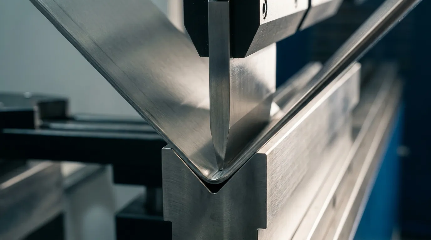
Key Takeaways
- Bending rules act as conditional starting points that shift with material, thickness, temper, tooling and forming method.
- Bend allowance, bend deduction and K-factor calculations set flat pattern accuracy and prevent cumulative dimensional drift.
- Bend method selection changes achievable radius, tonnage, springback and tolerance capability for the same drawing.
- Tolerance works best when specified by feature type instead of a single blanket callout across the print.
- Request a Fabcon DFM review to align bend rules, tooling and tolerances before releasing drawings.
Core Sheet Metal Bending Rules For Press Brake Work
These six rules form the baseline for press brake forming of common structural sheet metals. Each rule pairs a numeric anchor with the condition that shifts it, and later sections explain when each one no longer applies.
- Inside bend radius minimum: keep the inside radius at least one times material thickness for most low-carbon steel and aluminum alloys. Tighter radii increase cracking risk on the outer bend surface.
- Hole-to-bend distance: place hole edges at least two and one-half times material thickness plus the inside bend radius from the bend line for holes under 25 mm in diameter. Larger holes and slots need more clearance.
- Slot-to-bend distance: keep slot edges at least four times material thickness plus the inside bend radius from the bend line. Slots distort more readily than round holes in the deformation zone.
- Minimum flange length: size flanges at least four times material thickness so the sheet spans the V-die opening and makes stable contact with both die shoulders.
- Grain direction: orient the bend line perpendicular to the sheet’s rolling direction. Bending parallel to grain increases crack risk on moderate-ductility materials, and on low-ductility alloys it can be the difference between a clean bend and a scrapped part.
- Springback allowance: program an overbend equal to the measured springback for the material, thickness and bend method in use. A single compensation value rarely fits every combination.
These rules provide a working baseline. The next sections show when each rule shifts and how to choose better numbers.
Sheet Metal Bend Radius Guidelines For Common Alloys
The one times material thickness rule holds for mild steel (cold-rolled, 1008/1010) and 5052-H32 aluminum. Both materials carry enough ductility to sustain the outer-fiber tensile strain at that radius without cracking. Other common alloys need larger inside radii.
Mild steel (cold-rolled): Minimum inside bend radius for 1018 cold-rolled mild steel runs from one-half times material thickness at thin gauges to one and one-half times material thickness at thicker gauges. The multiplier steps up as thickness increases. Hot-rolled mild steel requires more clearance because surface scale and thickness variation increase forming risk.
304 stainless steel: Annealed 304 stainless requires a minimum inside bend radius of one-half times material thickness at thin gauges, rising to two times material thickness at thicker gauges. The alloy work-hardens rapidly during forming, which shifts the neutral axis inward and increases springback relative to mild steel. A practical starting point for 304 stainless is one and one-half to two times material thickness for material in the 1–6 mm range.
5052-H32 aluminum: 5052-H32 carries a minimum inside bend radius of one-half times material thickness at thin gauges and one and one-half times material thickness at thicker gauges. This behavior makes it the preferred aluminum alloy for formed parts. Its ductility and corrosion resistance often allow direct substitution for 6061-T6 in bending applications.
6061-T6 aluminum: 6061-T6 requires a minimum inside bend radius of two times material thickness at 0.5–1.0 mm, rising to six times material thickness at thicker gauges. The alloy carries a high cracking risk rating. Its high yield strength (276 MPa) and low elongation (approximately 12%) make it the most crack-prone alloy in standard press brake work. Bending with the grain rather than across it compounds the problem, increasing the required radius by a penalty factor of 67–100% on 6061-T6. Annealing to O temper before forming reduces the required radius to one to two times material thickness, though strength is lost unless re-heat-treated afterward.
Tooling geometry sets hard limits on achievable radius regardless of what the drawing specifies. In air bending, the inside radius is approximately 0.16 times the die opening width for mild steel. A punch tip radius smaller than the natural air-bent radius still produces the radius the die opening dictates. Achieving a tighter radius than air bending naturally produces requires bottoming or coining, which demand significantly higher tonnage and matched tooling.
Validate bend radii with Fabcon’s engineering team against real tooling before the drawing is released.
Sheet Metal Bending Calculation For Flat Patterns
Once the bend radius is set, the next step is translating that radius into a flat pattern. The bend allowance (BA) is the arc length along the neutral axis through the bend. It determines the flat blank length needed to produce correct finished dimensions after forming.
The standard bend allowance formula, documented in Machinery’s Handbook, 31st Edition (Industrial Press, 2020), is:
BA = (π ÷ 180) × A × (R + K × T)
Where A is the bend angle in degrees, R is the inside bend radius in mm, K is the K-factor (dimensionless) and T is the material thickness in mm.
The K-factor is the ratio of the neutral axis position, measured from the inside bend surface, to material thickness. As documented in the ASM Handbook, Volume 14B: Metalworking Sheet Forming (ASM International, 2006), the neutral axis migrates inward during plastic deformation, so K is less than 0.5 in almost all practical press brake work. K-factor varies with material ductility, the radius-to-thickness ratio (r/t) and bend method. Air bending typically yields K = 0.38–0.45, bottoming K = 0.36–0.42 and coining K = 0.30–0.35.
Worked example: 2.0 mm mild steel (cold-rolled), 90° bend, inside radius R = 2.0 mm (1×T), assumed K = 0.42 for air bending at r/t = 1.
- BA = (π ÷ 180) × 90 × (2.0 + 0.42 × 2.0)
- BA = 1.5708 × (2.0 + 0.84)
- BA = 1.5708 × 2.84
- BA = 4.46 mm
Bend deduction (BD) is the complementary value used in flat pattern development when working from outside dimensions. BD = 2 × OSSB − BA, where outside setback OSSB = (R + T) × tan(A ÷ 2). For the example above: OSSB = (2.0 + 2.0) × tan(45°) = 4.0 mm, BD = 2 × 4.0 − 4.46 = 3.54 mm. Both methods produce the same flat blank dimension when the same K-factor is used.
Using the CAD default K = 0.44 instead of the correct K = 0.42 for this condition creates a 0.38 mm error per bend, compounding to over 3 mm of dimensional drift on an 8-bend enclosure. Verifying the flat pattern against the shop’s actual tooling and material lot before releasing the drawing prevents that drift. The most reliable K-factor is measured empirically on a test strip of the production material bent on the production die.
Minimum Flange Length And Bend Relief Rules
The minimum flange length in press brake work is at least four times material thickness. The sheet must span the V-die opening and make stable contact with both die shoulders. A flange shorter than the die can grip will slip, deform and produce an inconsistent bend angle. The minimum flange must also be at least as wide as the die V-opening, whichever is larger.
Die opening width, material thickness and flange geometry all shift this minimum. A 2.0 mm sheet bent in a 16 mm V-die produces a minimum flange of approximately 11.0 mm, which sits well above the four times material thickness floor of 8.0 mm. In that case, the die opening becomes the binding constraint.
Bend relief is required wherever a bend terminates near an adjacent wall, cutout or edge. Without a relief notch, the material bunches at the corner and tears or distorts uncontrollably. Bend relief width must be at least material thickness and depth must be at least inside bend radius plus material thickness. Relief cuts approximately one and one-half times material thickness wide prevent tearing at bend corners and uncontrolled deformation at flange edges.
Air Bending, Bottoming And Coining In Comparison
The bend method determines achievable inside radius, required tonnage and springback. The same drawing can produce different results depending on which method the shop uses.
Air bending contacts the material only at the punch tip and the two V-die shoulders. The final bend angle is controlled by punch penetration depth, and one punch-and-die set can produce many different angles. The inside radius is governed by the die opening and material properties, not the punch tip alone. Air bending requires the least tonnage but produces the most springback, particularly in stainless steel and high-strength alloys. CNC press brakes compensate with programmed overbend.
Bottoming drives the sheet deeper into the die so the material contacts the die geometry more completely. Bottoming requires approximately four to five times the tonnage of air bending for the same material and die opening. The method delivers tighter angle repeatability and less springback. It is generally recommended only up to approximately 3 mm thickness because tonnage demands increase sharply beyond that point.
Coining plastically compresses the material into the punch-and-die geometry under high force. Coining may require six to ten times air-bending tonnage and produces the tightest, most repeatable angles with minimal springback. It demands dedicated tooling and suits parts that justify that investment rather than flexible, high-mix production.
Bending method tolerances differ materially: air bending holds approximately ±0.3 mm on angle, bottoming ±0.15 mm and coining ±0.05 mm. Specifying a process method on the drawing, or confirming it with the fabricator before release, keeps the method aligned with the tolerance requirement.
Bending Tolerance: How To Specify It On A Drawing
Bending tolerance covers bend angle, flange length and hole-to-bend position. Standard bend angle tolerance is ±1.0°–2.0°, while precision tolerance is ±0.5°. For flanges ≤ 100 mm, standard flange length tolerance is ±0.3 mm and precision is ±0.15 mm.
Tolerance capability depends on material, thickness, tooling and bend method. ISO 2768 sets general tolerances for linear and angular dimensions where no callout is given, while ASME Y14.5 governs GD&T for form, orientation and position. Naming one standard in the title block sets the tolerance for every uncalled dimension.
Tight angle tolerances interact with bend radius: a tighter radius makes angle harder to control, so specifying both a tight radius and a tight angle simultaneously becomes a common drawing mistake. Bend tolerance also interacts with the flat pattern, because the K-factor used in CAD must match the shop’s empirical value or the flat pattern will be wrong before the first bend is made. When a bend radius is in question, ASTM E290 provides the standard method for evaluating material bendability. Consulting the fabricator before locking in tight tolerances keeps the print aligned with real capability.
Sheet Thickness Limits For Press Brakes And Hand Bending
Press brake capacity depends on machine tonnage, die opening, material tensile strength and bend length. Required tonnage increases roughly with the square of material thickness, so doubling thickness can increase the necessary force by approximately a factor of four. Gauge designations vary by material, and 16 gauge is 1.52 mm in steel and 1.29 mm in aluminum, so rule-of-thumb multipliers apply to actual measured thickness, not gauge number.
Manual and hand bending stay bounded to thin gauges and soft materials. Achievable bend length is short, angle consistency is poor and the inside radius is difficult to control. Heat is sometimes applied to reduce forming force on thicker or harder stock, but it changes material properties and does not match press brake work for structural or tolerance-critical parts. Hand bending remains a narrow exception rather than a production method.
Confirm press brake capability for a specific part before committing to a design that pushes thickness limits.
Applying Sheet Metal Bending Rules With Fabcon
Bending rules only hold when the shop applies them consistently across material, tooling and process. A fabricator who treats bend radius as a fixed constant rather than a conditional value will produce parts that drift from the drawing when material temper, grain direction or die selection changes.
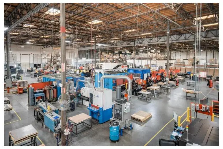
Fabcon is an engineering-led fabrication partner that applies sheet metal bending rules correctly from prototype through production. Fabcon’s in-house engineering and DFM collaboration reviews drawings, tolerances and materials before production begins, so bend radii, flange lengths and bend relief are validated against real tooling. That review catches the conditions that override the standard rules: temper, grain direction, die opening and bend method.
Fabcon’s vertically integrated capabilities, including precision sheet metal fabrication, CNC machining, finishing and light electromechanical assembly, operate under one roof. That structure eliminates vendor handoffs and keeps bend rules consistent across the full build. Fabcon’s quality systems are ISO 9001:2015 and AS9100D certified with ITAR registration and full traceability across every part. Agile production cells support high-mix, mid-volume programs without the rigidity or high minimums of large contract manufacturers.
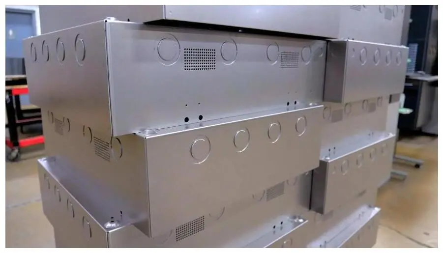
Request a DFM review before the next production release to align design intent with real forming conditions.
Frequently Asked Questions
What Is the Bend Allowance for Sheet Metal?
Bend allowance is the arc length along the neutral axis through a bend. It is calculated as BA = (π ÷ 180) × A × (R + K × T), where A is bend angle in degrees, R is inside bend radius, K is the K-factor and T is material thickness. The worked example earlier in this article shows a 90° bend on 2.0 mm mild steel producing a bend allowance of 4.46 mm. The value changes with material, bend method and the K-factor used.
What Is the Minimum Flange Length for Sheet Metal?
The minimum flange length is ≥ 4×T, or four times material thickness, as a starting rule. The actual minimum is whichever is larger: 4×T or the die V-opening width divided by two plus material thickness. A shorter flange cannot span the die shoulders and will deform or slip during forming.
What Is the Bending Tolerance for Sheet Metal?
Standard bend angle tolerance is ±1.0°–2.0° for air bending. Precision work achieves ±0.5° with bottoming and ±0.05° with coining. Flange length tolerance is typically ±0.3 mm standard and ±0.15 mm precision for flanges under 100 mm. Tolerance capability depends on material, thickness, tooling and bend method, and tighter callouts should be confirmed with the fabricator before the drawing is released.
How Thick of Sheet Metal Can You Bend?
Press brake capacity sets the practical limit, and that limit depends on machine tonnage, die opening, material tensile strength and bend length. Required tonnage increases roughly with the square of material thickness. The fabricator’s machine and tooling ratings determine what is achievable for a given material and bend geometry.
Should You Heat Metal Before Bending It?
Hot bending reduces forming force and can allow tighter radii on materials that crack in cold forming, such as thick high-strength steel. For peak-hardened heat-treatable aluminum alloys like 6061-T6, hot forming degrades mechanical properties and requires subsequent heat treatment to restore them. Heat changes material properties, can affect temper and does not represent a standard press brake process. For most structural sheet metal work, a better approach is to select a more ductile alloy or temper, increase the bend radius or add bend relief rather than applying heat.
What Is the K-Factor in Sheet Metal Bending?
The K-factor is the ratio of the neutral axis position, measured from the inside bend surface, to material thickness. Its practical range varies by bend method and radius-to-thickness ratio, as described in the bending calculation section. K-factor depends on material ductility, the radius-to-thickness ratio and bend method. The most reliable K-factor is measured empirically on a test strip of the production material bent on the production tooling.
What Is the Difference Between Bend Deduction and Bend Allowance?
Bend allowance is the arc length added to the flat legs to produce the correct blank length. Bend deduction is the amount subtracted from the sum of outside flange dimensions to arrive at the same flat blank length. Both methods produce the same result when the same K-factor is used. CAD systems vary in which method they apply, so the K-factor input must match the shop’s empirical value to avoid flat pattern errors.
What Is Bend Relief in Sheet Metal?
Bend relief is a notch cut at the end of a bend line where it terminates near an adjacent wall, edge or cutout. Without relief, the material bunches and tears at the corner during forming. Relief width must be at least equal to material thickness (T) and depth must be at least R + T, where R is the inside bend radius. Bend relief is required on any part where a bend line runs close to a perpendicular feature or the sheet edge.
Conclusion And Next Steps
Sheet metal bending rules, including inside radius, hole-to-bend distance, minimum flange length, grain direction and springback, provide practical starting points. Material grade and temper, tooling geometry and bend method determine the real number for every feature on the drawing.
Effective next steps include verifying the flat pattern against the shop’s actual tooling and K-factor, confirming bend method and springback compensation with the fabricator and specifying bending tolerance deliberately by feature type instead of a single blanket callout.
Fabcon’s engineering team reviews drawings, tolerances and materials before production begins and applies these rules against real tooling from prototype through production. Request a Fabcon DFM review and align the next release with proven forming practice.