
Key Takeaways for Sheet Metal Tolerances
- Targeted tight tolerances on critical sheet metal features control cost and lead time while still protecting function.
- Four recurring failure modes, including tolerance stack-up and springback variation, arise when machining-grade tolerances are applied to formed parts.
- A tiered tolerance strategy with ISO 2768-mK defaults reduces special processes, inspection time and scrap.
- DFM rules for hole-to-bend distance, bend radii, flange length, bend relief and grain direction prevent distortion and rework.
- Early collaboration with an integrated fabricator like Fabcon aligns tolerances with real capability and supports smooth scale-up.
The Problem: Blanket Tight Tolerances on Sheet Metal Prototypes
Sheet metal fabrication relies on forming, not machining. Press brakes, laser cutters and CNC punches introduce process variation that differs from milled or turned parts. Applying machining-grade tolerances to formed features conflicts with that reality.
Four failure modes appear repeatedly on drawings with indiscriminate tight callouts.
Tolerance stack-up. Hole patterns that span multiple bends accumulate variation from each bend. Dimensions that cross two or more bends often exceed tight callouts through forming alone. Post-forming operations become necessary when drawings ignore this accumulation.
Springback variation. Springback in sheet metal changes with material type and batch. Yield strength variation means springback does not stay constant. Even within a single grade, test bends on production material provide more reliable data than formulas alone.
Hole-to-bend distortion. Holes placed too close to a bend line distort during forming. The minimum safe distance from a hole edge to the bend line depends on material thickness and inside bend radius. When this rule is ignored, holes become oval and shift position, and no tolerance callout can repair that damage later.
Indiscriminate spec application. Tight tolerances on formed flange dimensions increase part cost when the flange function does not require that precision. Applying machining tolerances to formed features remains a common and expensive mistake.
These failure modes share a common root cause. Tolerances tighter than standard sheet metal capability often demand extra operations and increase part cost. Vendor handoffs grow when one shop cannot meet the spec, which fragments accountability and extends lead time.
The Solution: Focus Tight Tolerances on Functional Features
An effective tolerance strategy reserves tight callouts for mating interfaces and functional datums, then applies process-appropriate tolerances everywhere else.
A tiered tolerance structure improves cost control. Critical mating interfaces receive the tightest callouts. Important features receive moderate callouts. Standard features follow general tolerances. Non-critical areas carry the widest tolerances. This structure reduces the number of features that need special process control and detailed inspection.
Material-specific springback compensation supports any tight angular callout. The compensation method affects both achievable tolerance and process cost.
- Air bending produces higher springback controlled by stroke depth. It offers flexible tooling but carries the widest angular variation.
- Bottoming reduces springback compared with air bending by applying more tonnage. It improves angular consistency but requires a heavier press.
- Coining further reduces springback by deforming the material through the thickness. It delivers the tightest angles but increases tonnage demand and die wear.
Bend radius rules also influence springback. Larger bend radii increase springback because more of the sheet thickness stays in elastic deformation. Consistent bend radii across a part make springback behavior more uniform and easier to compensate.
Post-machining of mating faces becomes the right choice when formed tolerances alone cannot meet assembly requirements. Sheet metal prototyping combined with secondary CNC machining on specific datum faces delivers both formed geometry and tight control where needed. This hybrid approach costs less than forcing machining-grade tolerances through forming on every feature.
Process-Based Tolerance Guidance for Sheet Metal
The following section describes realistic process capabilities on well-maintained equipment. These capabilities guide tolerance decisions during drawing review.
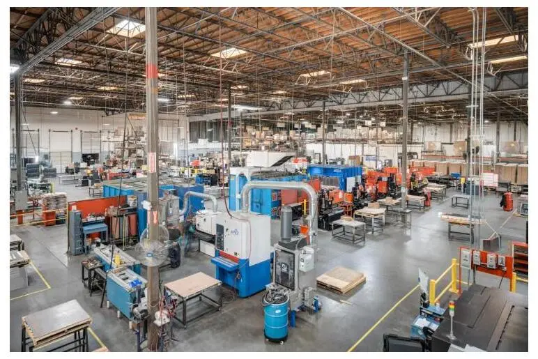
Laser cutting. On well-calibrated fiber laser equipment, positional accuracy depends on material type, thickness and feature geometry. Features cut on the same flat surface often hold tighter tolerances than formed dimensions. Thicker material widens the achievable range.
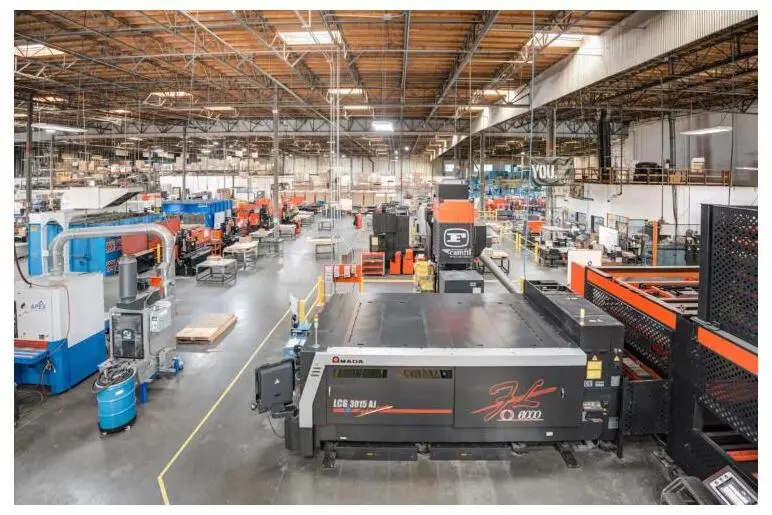
CNC punching. CNC-punched holes and profiles typically meet standard tolerances. Hole position depends on tool condition, material and clearance between punch and die.
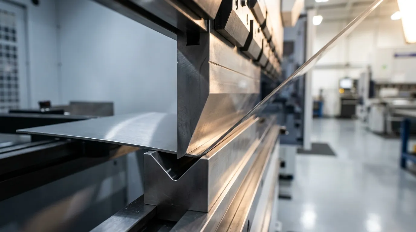
Press-brake bending. Advanced CNC press brakes with closed-loop control commonly achieve consistent bend angles under standard conditions. Bend-to-bend and overall formed dimensions follow standard sheet metal tolerance ranges rather than machining ranges.
Flatness and angular tolerances. ISO 2768-mK provides a practical general tolerance class for most sheet metal components. The “m” class covers medium linear tolerance and the “K” class covers medium geometric tolerance. Together they reflect realistic press brake capability without unnecessary cost.
A drawing checklist for quick reference follows a logical sequence.
Start by applying ISO 2768-m in the title block as the default for non-critical features. This step establishes a realistic baseline. From that baseline, call out tight tolerances only on mating interfaces and functional datums that require precision. When specifying bend angles, state the final formed angle on the drawing, not the punch angle, because springback compensation belongs to the fabricator. Separate flat-feature tolerances from formed-feature tolerances, since each category reflects different process capability. Finally, account for laser kerf width in the cut file for critical dimensions so the finished part aligns with design intent.
DFM Rules That Prevent Distortion and Rework
Design-for-manufacturability rules for sheet metal are well established. Applying them at the prototype stage prevents recurring problems in production.
Hole-to-bend distance. The minimum hole-to-bend distance depends on material thickness and bend radius. This distance protects holes from deformation during forming. When a hole must sit inside this safety zone, drilling or punching after bending avoids ovaling, tearing and positional shift.
Minimum bend radius by material. Minimum inside bend radius changes with alloy and temper. Heat-treated aluminum alloys such as 6061-T6 and 7075-T6 require larger radii than mild steel or annealed aluminum because heat treatment reduces ductility. Material-specific DFM guidelines or fabricator input help define appropriate radii for each application.
Flange length. Minimum flange length should equal several times material thickness. Shorter flanges can slip out of the back gauge during bending, which disrupts accuracy and fixture repeatability.
Bend relief. Intersecting bends need a relief notch. Relief width should be at least material thickness, and depth should cover at least bend radius plus material thickness. This geometry prevents material from bunching and bulging in uncontrolled ways.
Grain direction. Bending parallel to the sheet metal grain increases springback and cracking risk compared with bending perpendicular to the grain. Parallel bending often requires a larger minimum bend radius to protect the material.
Bending method selection. Air bending suits most standard geometries and offers tooling flexibility. Bottoming fits cases where angular tolerance matters and the added tonnage remains acceptable. Coining serves the tightest angular requirements on features where higher die wear cost aligns with functional needs.
Aligning Prototype and Production Tolerances
Tolerances defined at the prototype stage flow into production tooling, inspection plans and supplier agreements. Unrealistic prototype specs create compounding issues as volume grows.
Applying DFM guidelines on the sheet metal drawing reduces fabrication cost compared with designs that ignore manufacturing limits. Early DFM review exposes tolerance conflicts before tooling or production routers lock in those decisions.
Fixtures and jigs can tighten specific features such as weld assemblies or multi-bend parts. This targeted approach avoids tight tolerances across an entire part and scales more reliably than relying only on process control.
Single-partner control over fabrication, finishing and assembly keeps tolerance stack-up visible and manageable. When a part moves between vendors for forming, coating and assembly, each transfer introduces handling variation and accountability gaps. Integrating those steps under one roof with one quality system maintains clear ownership and earlier correction.
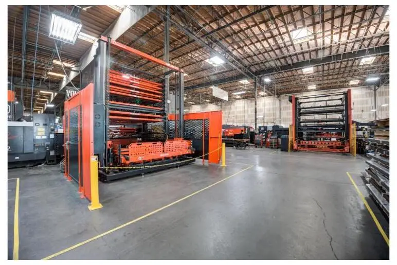
Fabcon’s ISO 9001:2015 and AS9100D certified quality system covers fabrication through final assembly. First-article inspection, change control and full traceability operate as standard practices. That structure supports prototype-to-production scaling without requalifying a new supplier at each volume step.
Due-Diligence Checklist for Precision Sheet Metal Partners
Selecting a fabrication partner for tight-tolerance sheet metal work requires more than a capability statement. The following checklist covers core criteria for programs in infrastructure, aerospace, defense, medical and energy storage applications.
- Quality certifications: ISO 9001:2015 for general quality management, AS9100D for aerospace and defense programs, ITAR registration for controlled-technology parts.
- Traceability: Material certifications, lot tracking and dimensional records tied to each part number and revision.
- First-article inspection: CMM-based FAI with dimensional report issued before production release.
- Change control: Documented engineering change process with revision history and customer notification at defined thresholds.
- In-house finishing and assembly: Powder coat, wet paint, mil-spec coating and light electromechanical assembly under the same roof as fabrication to avoid inter-vendor variation.
- DFM collaboration: Engineering support available before drawing release to review tolerances, bend sequences and material selection.
- Scalability: Production cell structure that supports prototype quantities and mid-volume production without requalification or restrictive minimum orders.
Key questions before releasing a drawing keep expectations aligned.
- Which tolerances on this drawing require secondary machining to achieve?
- What springback compensation method applies for this material and thickness?
- Do all hole-to-bend distances meet DFM minimums for this material?
- Does the quality system include FAI and CMM reporting as standard practice?
- Can the same partner handle finishing and assembly, or will the part transfer to another vendor?
Frequently Asked Questions
What is the standard tolerance for sheet metal?
Standard tolerances for sheet metal depend on process and feature type. Laser-cut features on a flat surface often hold tighter tolerances than formed dimensions. Press-brake bend angles commonly achieve ±1 degree under standard conditions, with tighter results possible on CNC equipment with closed-loop angle feedback. Flange lengths and bend-to-bend dimensions carry wider tolerances than flat-cut features because forming introduces variation that accumulates across bends. ISO 2768-m serves as a widely accepted general tolerance standard for sheet metal drawings. It covers linear and angular dimensions that match press-brake capability and removes the need to tolerance every non-critical dimension. Critical mating features should receive explicit tighter values, while non-functional edges and cosmetic surfaces retain the ISO 2768-m default.
What is considered a tight flatness tolerance for sheet metal?
Flatness tolerance in sheet metal depends on material thickness, part size and the number of forming operations. For laser-cut flat blanks, flatness mainly reflects material residual stress and sheet quality. For formed parts, each bend introduces angular variation that affects overall flatness. ISO 2768-mK addresses both linear and geometric tolerances, including flatness, at a level consistent with standard press-brake capability. Tolerances tighter than the forming process can deliver require post-forming steps such as straightening, fixturing during welding or secondary machining of reference surfaces. Specifying flatness on a formed enclosure at the same level as a machined plate often drives unnecessary cost and rework. The appropriate flatness callout should match the assembly function of the surface.
What is the rule of thumb for sheet metal bend radius?
The minimum inside bend radius depends on material type and temper. Mild steel and 5052-H32 aluminum tolerate tighter radii than stainless steel or heat-treated aluminum alloys. Aluminum 6061-T6 needs a larger minimum radius than mild steel because the heat-treated condition reduces ductility. Bending parallel to the grain direction requires a larger minimum radius than bending perpendicular to the grain and raises cracking risk in aluminum and high-strength steels. Using a consistent bend radius across all bends on a part supports a single tool setup, reduces cost and makes springback compensation more uniform. When a tighter radius is functionally required, consultation with the fabricator before drawing release helps clarify tonnage and tooling impact on lead time and cost.
When does post-machining become necessary for tight tolerances?
Post-machining becomes necessary when the required tolerance on a mating feature exceeds what forming can deliver consistently. Press-brake bending and laser cutting each have inherent variation floors. When a functional interface such as a connector mounting face, bearing bore or precision datum surface needs tighter control than forming can provide, secondary CNC machining of that feature after forming becomes the appropriate solution. This hybrid approach keeps the cost benefits of sheet metal for overall geometry while achieving the accuracy needed at the interface. Post-machining works best when limited to one or two critical features that truly require it, while all other dimensions follow process-appropriate sheet metal tolerances.
Conclusion: Sheet Metal Drawings That Build Cleanly
Over-tolerancing sheet metal prototypes does not improve part quality. It raises cost, extends lead time and creates rework cycles that slow production scaling. A reliable path to functional precision uses a targeted tolerance strategy, with tight specs at mating interfaces, process-appropriate tolerances elsewhere and DFM collaboration before drawing release.
Fabcon supports that process from first drawing review through production delivery. With ISO 9001:2015 and AS9100D certified quality systems, in-house fabrication, finishing and light electromechanical assembly across U.S. manufacturing space, Fabcon provides integrated accountability that fragmented supply chains cannot match. Programs in data centers, energy storage, aerospace and defense, medical devices and EV infrastructure benefit from a single partner that controls every step from prototype to production.
Get a quote and start the DFM conversation before releasing the next drawing.