
Key Takeaways for 19-Inch Telecom Chassis
- Telecom chassis fabrication demands precise 19-inch rack enclosures that meet EIA-310-D standards while managing heat and EMI shielding.
- Material choice between aluminum and steel shapes thermal performance, structural strength, EMI behavior and corrosion resistance for each program.
- Core processes such as laser cutting, CNC forming, welding and finishing work best under one quality system that avoids vendor handoff risk.
- Thermal and EMI performance link closely, so vent design, gaskets and grounding must be coordinated to avoid common EMI test failures.
- Partner with Fabcon for vertically integrated telecom chassis fabrication from DFM review through production under one quality system.
Choosing Materials for Telecom Chassis Performance
Material choice sets the baseline for heat flow, stiffness, EMI shielding and corrosion resistance. Telecom chassis programs most often use aluminum or steel alloys, each with clear tradeoffs.
Aluminum alloys such as 5052 and 6061 provide higher thermal conductivity than mild steel, so chassis walls act as effective heat spreaders. Fin geometry and high-emissivity anodized finishes can lower internal temperatures compared with bare or painted surfaces. Aluminum also weighs less than steel at the same envelope, which cuts freight cost and supports higher rack density for edge or high-density deployments. For EMI performance, aluminum 6061-T6 shields well across RF frequencies above 1 MHz, but it needs chromate conversion coating or conductive gaskets at seams because the natural oxide layer is nonconductive.
Cold-rolled steel delivers higher elastic modulus and yield strength than aluminum, so it suits chassis that carry heavy loads such as dense drive arrays or power supplies. This structural benefit pairs with useful electromagnetic behavior. Mild steel’s higher relative permeability improves magnetic shielding below 100 kHz, where aluminum performs poorly. For production efficiency, electro-galvanized steel grades support reliable EMI continuity with limited extra processing. When corrosion resistance outweighs cost, stainless steel 304 becomes the preferred choice for outdoor telecom enclosures.
Some programs need both strong structure and passive heat spreading. Hybrid designs that use a steel structural frame with aluminum covers can meet that need but add assembly steps and inventory complexity. The final material decision should reflect power density, mounting load, operating environment and EMI frequency range for the specific program.
Core Fabrication Processes for 19-Inch Rack Chassis
Telecom chassis fabrication depends on a linked sequence of processes that protect dimensional accuracy across the full assembly. Once material is set, that choice guides bend behavior, heat input during welding and finishing options.
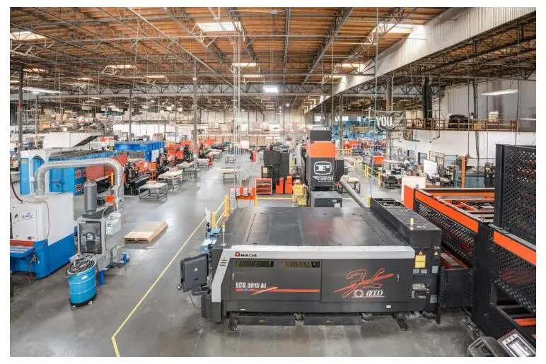
- Laser cutting: Fiber laser cutting produces tight-tolerance blanks for panels, rails and vent patterns. These tolerances support EIA-310-D hole pattern compliance and consistent fit across racks.
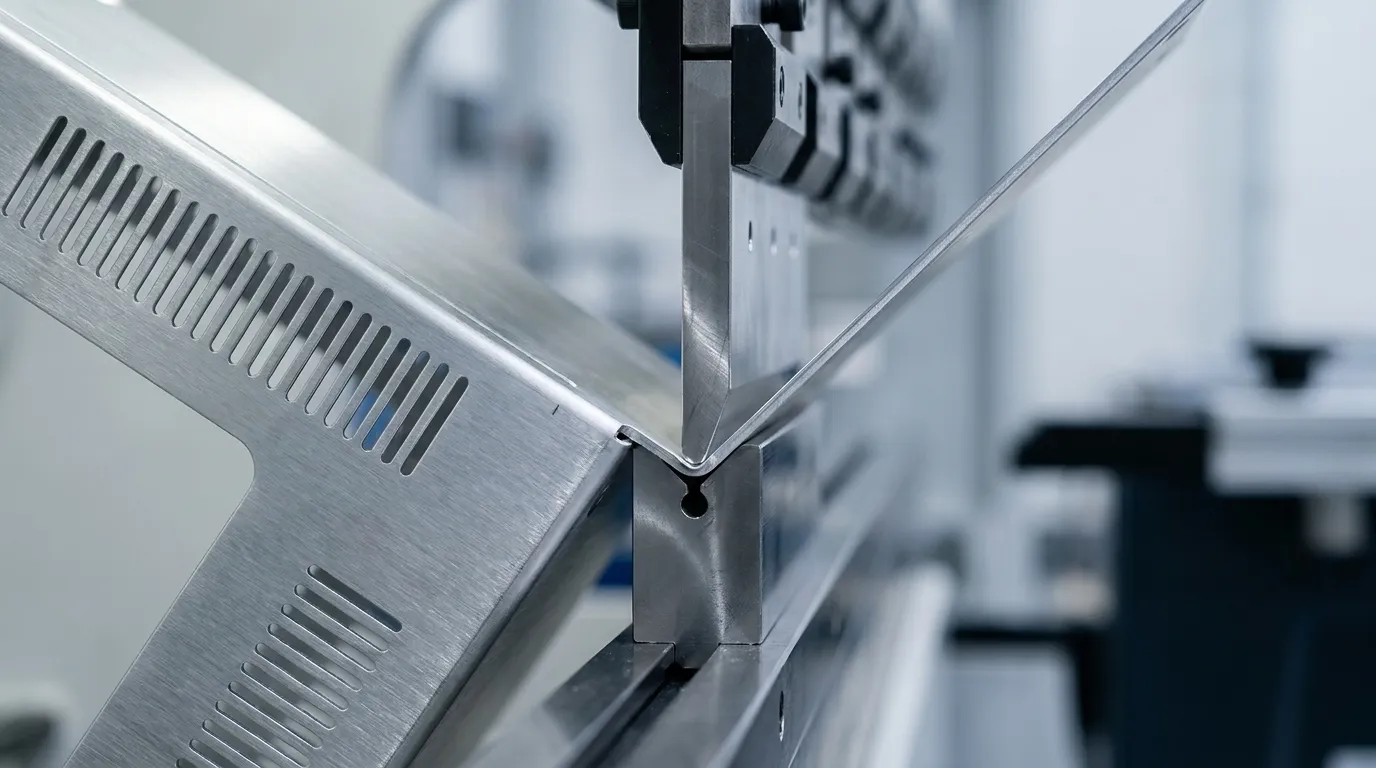
- CNC press brake bending: Flanges, rails and enclosure profiles require accurate bend deduction calculations. In tall rack assemblies, small bend errors can stack and create misalignment at the top of the frame. Bend deduction should be calculated per material, gauge and tooling rather than pulled from generic tables.
- Welding and fastening: Structural corners, sealed seams and high-load brackets use certified welding. Tabs, fasteners, rivets and clinch features work well where they meet load, sealing and service needs. Limiting welding to locations that truly need it reduces distortion and grinding cost.
- Finishing: Powder coat, wet paint, anodizing and conductive coatings protect the chassis and, when needed, restore EMI continuity. Powder-coated joints need masked ground-stud locations or thread-forming hardware because coating acts as an insulator at grounding points.
Keeping these processes under one roof removes vendor handoffs that often create dimensional drift, finish variation and schedule risk.
Balancing Thermal Management and EMI Shielding
Thermal and EMI performance interact in telecom chassis design. Vent features that improve airflow can weaken shielding if design teams treat them separately.
For thermal management, perforated doors need a minimum open area that supports hot-aisle and cold-aisle airflow for active IT loads per ANSI/BICSI 002. Hex perforation patterns often provide higher open area and better stiffness than round patterns at the same pitch. Higher-density deployments may add rear-door heat exchangers or direct liquid cooling manifolds, which improve heat removal but raise cost and introduce leak-management requirements.
For EMI control, honeycomb vent panels or fine mesh outperform plain louvers because open louvers act as EMI leak points. Thermal and EMI vent designs should be resolved together. At gasketed seams, tight fastener pitch with conductive overlap at joints maintains uniform gasket compression and limits slot leakage. The base-lid seam often becomes the most critical seam and typically uses continuous weld or finger stock for enclosures that open often.
Many electronic devices fail initial EMI testing, which raises cost when shielding issues surface after fabrication. Early DFM collaboration that treats thermal and EMI needs as a single design problem reduces late-stage redesign.
Key 19-Inch Rack Dimensions and Constraints
EIA-310-D and CEA-310-E define the dimensional rules that keep 19-inch rack chassis interoperable. Engineering and procurement teams should confirm compliance against several core parameters.
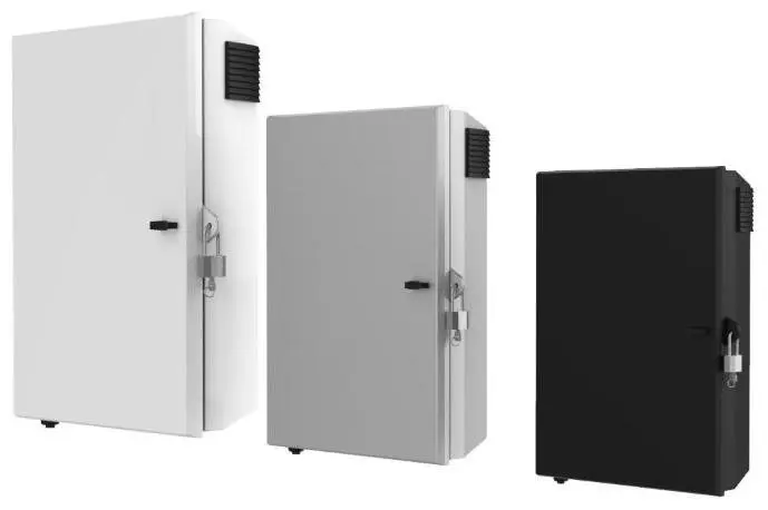
- Front panel width: Total width is 482.6 mm, with 450.85 mm between vertical posts and 0.625-inch flanges on each side.
- Rack unit height: One rack unit equals 1.75 inches. Panel height must be an exact multiple of 1U with slight clearance to avoid jamming.
- Mounting hole pattern: Vertical spacing repeats every 1U in a 5/8-inch, 5/8-inch, 1/2-inch pattern, with horizontal rail separation of 465.1 mm.
- Mounting hole types: Compliant four-post racks may use square 0.38-inch, round 0.28-inch, #12-24 UNC or #10-32 UNC holes.
- Depth: Rack depth is not standardized and often ranges from 24 to 48 inches, so teams must confirm fit against cabinet and cable needs.
- Load ratings: Static load ratings for floor-standing 42U cabinets often range from 1,500 to 3,000 pounds, with seismic programs referencing GR-63-CORE Zone 4 or similar standards.
- Inlet temperature: ASHRAE TC 9.9 Class A1 calls for an optimum server inlet temperature of 18 to 27 degrees Celsius, measured at the server front.
DFM Practices That Protect Telecom Chassis Programs
Design-for-manufacturability collaboration between engineering and fabrication teams delivers strong leverage in telecom chassis programs. Problems solved during DFM cost far less than changes made after tooling or production start.
Tight tolerances should focus on functional interfaces such as mounting hole patterns that locate parts in rackmount chassis. General sheet-metal tolerances can follow ISO 2768-m, with tighter callouts reserved for grounding surfaces, sealing edges and locating features.
Key DFM topics for telecom chassis include:
- Bend radii: Inner bend radius should be at least equal to sheet thickness, with aluminum often needing a larger radius to avoid cracking.
- Hole placement: Hole-to-bend distance should be at least two to three times sheet thickness to limit deformation during bending.
- PEM hardware: Hardware placement must allow tool clearance, respect distance from bends and edges, and align with finish sequence and thread protection.
- Panel stiffening: Large flat panels benefit from ribs, flanges or embosses instead of thicker material, which helps avoid oil canning and resonance.
- Finish planning: Surfaces that need conductivity or grounding should be masked during powder coating, and cosmetic faces should be defined early.
- Inspection state: Free-state or restrained-state inspection should be specified for flexible panels so inspectors apply a consistent method.
Strong prototype-to-production alignment depends on resolving these points before the first article. Fabcon’s engineering and quoting teams work with customer technical teams before production, reviewing drawings, tolerances and materials to build routers that match the production floor.
Integrated Fabrication, Assembly and Logistics Flow
Mid-volume telecom chassis programs benefit from a partner that manages the full build sequence under one quality system. Splitting fabrication, finishing and assembly across vendors adds handoff delays, quality disputes and schedule risk.
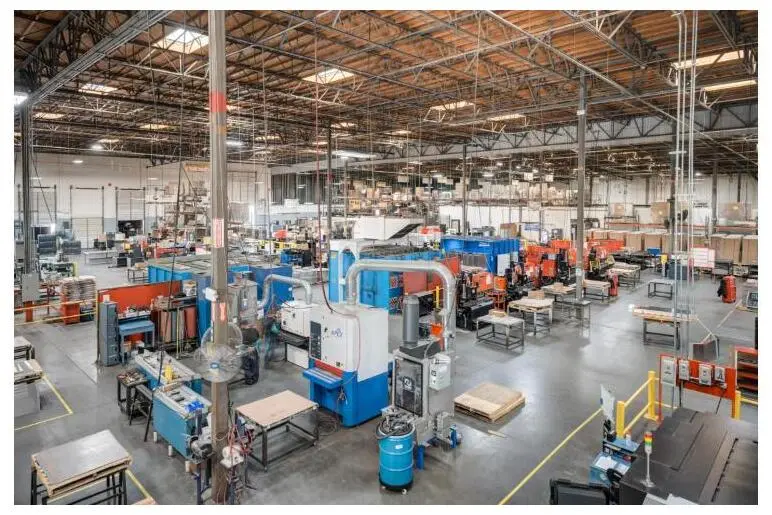
Fabcon’s integrated flow includes:
- Quoting and DFM review: Engineering and quoting teams review customer drawings together and flag manufacturability improvements before a purchase order.
- Precision fabrication: Laser cutting, CNC press brake forming, certified welding and CNC machining for tight features occur in-house.
- Finishing: In-house powder coat, wet paint, screen printing and conductive coatings follow defined cosmetic and grounding standards.
- Light electromechanical assembly: Hardware insertion, wiring and component integration take place in the same facility, which removes inter-vendor shipping.
- Quality and traceability: ISO 9001:2015 and AS9100D certified systems govern every stage and provide full part and lot traceability.
- Fulfillment and logistics: JIT delivery and fulfillment support program schedules without separate outbound logistics management.
One purchase order and one accountable partner simplify program control. Global supply chain disruption events rose 38% in 2024 compared with 2023, so each vendor handoff adds exposure. Consolidating fabrication, finishing and assembly under one roof reduces that exposure.
Get a quote and discuss a telecom chassis program with Fabcon’s engineering team.
Frequently Asked Questions
How should a program choose between aluminum and steel for a telecom chassis?
Aluminum excels in heat spreading and weight reduction, which supports edge deployments and high-density racks in demanding environments. Steel provides higher stiffness under heavy loads and strong low-frequency EMI performance with simpler surface treatments. Hybrid designs that combine a steel frame with aluminum covers can balance both sets of properties but add assembly and inventory complexity. The final choice should reflect power density, load, environment and EMI frequency targets for the program.
How does EIA-310-D compliance shape chassis fabrication tolerances?
EIA-310-D defines front panel width, mounting rail spacing, rack unit height and hole patterns that keep chassis and racks compatible. Meeting these dimensions requires tight control of laser cutting and CNC press brake operations, especially for hole position and panel height. The cumulative bend error issue described in the DFM section becomes critical in tall assemblies and calls for material-specific bend calculations. Panel height must match an exact multiple of 1U with slight clearance, and mounting hole patterns should be inspected in the restrained state with clear datums.
What EMI shielding issues appear most often in telecom chassis?
EMI problems most often start at seams, vents and grounding points rather than through panel material. Open louvers act as leak points and should give way to honeycomb vent panels or fine mesh. Gasketed seams need tight fastener pitch and conductive overlap to hold gasket compression. Powder-coated joints need masked ground-stud locations or thread-forming hardware, and anodized aluminum requires the masking approach described earlier to maintain shielding at joints. Addressing these topics during DFM review reduces the risk of late EMI test failures.
How does a vertically integrated U.S. fabricator reduce program risk?
A fragmented vendor base where fabrication, finishing and assembly sit with separate suppliers adds delay and quality variation at every handoff. Each transition creates a chance for dimensional drift, finish defects or missed assembly details. A vertically integrated partner manages fabrication, finishing and light electromechanical assembly under one quality system with one purchase order and one point of contact. This structure shortens quoting and production cycles, improves traceability and lowers coordination overhead for procurement and program teams.
Can a mid-volume telecom chassis program scale without shifting to a large contract manufacturer?
Large contract manufacturers often favor high minimum volumes and long onboarding cycles that do not match mid-volume, high-mix programs. Fabcon’s agile production cells support mid-volume work, scaling from prototype through production without the rigidity of large CMs. The same engineering and quality systems govern both prototype and production builds, so teams avoid separate qualification cycles. Programs that expect volume changes or BOM evolution gain flexibility from a partner whose structure adapts without new contracts or long lead times.
Conclusion: Next Steps for Telecom Chassis Programs
Telecom chassis that meet EIA-310-D, thermal and EMI requirements depend on early decisions about materials, DFM collaboration, tolerances and vendor structure. Working with a vertically integrated U.S. fabrication partner reduces handoff risk across the supply chain.
A practical next step is an internal review that documents chassis form factor, power density, EMI frequency range, production volume and schedule needs. With that detail, a fabrication partner can engage on DFM, material selection and production planning before a purchase order.
U.S. electronics production continues to grow, and reshoring strengthens when supply-chain risk, tariffs, compliance, IP protection and faster lead times outweigh the lowest offshore quote. For telecom and infrastructure OEM programs that face those pressures, domestic integrated fabrication-to-assembly offers a reliable middle path between job shops and rigid large CMs.
Fabcon has supported precision chassis and enclosure programs since 1977 and operates across 220,000 square feet of vertically integrated manufacturing space with ISO 9001:2015 and AS9100D certified quality systems. Engineering, fabrication, finishing and assembly stay under one roof from prototype through production.
Get a quote and start a telecom chassis fabrication program with Fabcon.