

Rear-Access Server Rack Enclosure Essentials
- Rear-access mechanisms in server rack enclosures directly affect aisle clearance, airflow and serviceability in constrained data-center environments.
- Door-style options such as hinged swing-gate, split-door and caster-mounted designs create distinct clearance and engineering tradeoffs that belong in early design reviews.
- Effective cable management and airflow practices, including sealed pass-throughs and disciplined routing, prevent hot spots and preserve front-to-back cooling.
- Co-location constraints and compliance requirements such as HIPAA, PCI-DSS and SOC 2 make early DFM collaboration and detailed RFQ specifications critical for successful deployments.
- Fabcon provides vertically integrated U.S. fabrication and custom rear-access rack enclosures built to program-specific requirements.
Rear-Access Server Rack Enclosures in Regulated Environments
A server rack enclosure with rear access is a fully enclosed cabinet with a controlled rear opening for cabling, maintenance and hardware servicing. Enclosed cabinets use solid side panels and lockable front and rear doors with gasketed or brushed cable entries. This configuration provides physical security, dust protection, acoustic damping and managed front-to-back airflow while meeting a specified IEC 60529 IP rating. Rear-access enclosures support compliance frameworks such as HIPAA, PCI-DSS and SOC 2 that require documented physical access controls alongside operational serviceability.
Rising rack densities increase the impact of rear-access design. AFCOM’s 2026 State of the Data Center report found that average rack density reached 27 kW per rack, up from 16 kW the prior year. At these power levels, rear-access geometry becomes a thermal and structural engineering challenge rather than a simple purchasing choice. Higher rack densities increase heat output, cable volume and equipment mass, which raises the stakes for rear clearance planning.
Clearance and Swing-Space Requirements by Access Mechanism
Clearance requirements depend on the access mechanism and the installation context. Project-specific equipment depth, cable bend radius and door thickness add to each baseline.
Wall-mounted hinged enclosures rely on three related clearance zones. A minimum rear standoff from the wall surface preserves ventilation by allowing air to enter the exhaust path. That standoff must also accommodate space behind the swing-out frame for hot-air exhaust and cable entry. Front door swing clearance and service aisle dimensions must then satisfy NFPA 70 working space requirements so technicians can work safely at the front while the rear remains against the wall.
Freestanding split-door and single-door enclosures depend on clear rear access. They require unobstructed rear clearance for full door swing and safe technician movement. Space at the back must align with rackmount specifications for the deepest installed equipment. Rear aisle width must also support cabling and maintenance access in line with general data-center layout guidance.
Caster-mounted swing-out designs shift the clearance problem to the floor plane. These designs require sufficient lateral floor space for the rack to pivot clear of adjacent cabinets or walls. Independent wheel brakes on casters for racks over 20U prevent movement under load. Cable service loops must be long enough to match the pivot radius without stressing connectors or bend radii.
Comparing Hinged, Split-Door and Caster-Mounted Rear Access
Each rear-access door style solves the clearance problem in a different way and introduces specific engineering considerations.
A hinged swing-gate door, on a wall-mount or freestanding cabinet, pivots on a single axis. The Eaton SRW15US swing-out frame and the StarTech RK1820WALHMCDW rear-hinge design follow this approach. The entire enclosure pivots away from the wall, which enables rear access where fixed rear clearance is limited. The tradeoff is a swing envelope that must remain clear at all times. A 180-degree door can still block access when the handle, hinge leaf, cable path, neighboring rack or wall enters the working area.
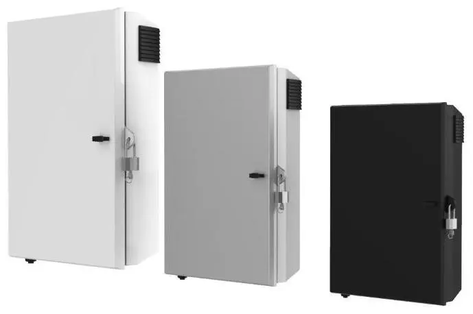
Split-door designs divide the rear opening into two independently hinged panels. Split rear doors reduce the swing envelope compared with one full-width rear door. They also introduce two hinge axes, two latch paths and a center meeting line that must stay aligned. One door panel may pass near a wall while the other crosses a cable manager or PDU. Perforation percentage influences thermal performance more than door count. Solid or glass rear doors trap heat regardless of configuration.
Caster-mounted designs move the entire rack laterally or rotationally to expose the rear. This approach removes the need for a dedicated rear service aisle and shifts focus to floor load ratings and cable slack management. Independent wheel brakes prevent tilting or rolling under load. Grounding continuity across the caster interface requires validation, and a dedicated bonding connection must carry that function instead of the hinge or caster contact.
Cable Management and Airflow in Tight Rear-Access Enclosures
Cable routing and airflow management interact directly in rear-access enclosures. The following practices address three common failure modes: cables blocking front intakes, unsealed pass-throughs and rear bundles that restrict exhaust.
- Seal open cable pass-throughs with brush panels or Flex Brush inserts to prevent hot exhaust from recirculating to the cold side.
- Dress cables into vertical side channels so the center rear exhaust path stays clear. A cable mass across the back dams hot air and creates hot spots that room-level cooling cannot resolve.
- Route power and data cables on separate pathways, with A and B power feeds on opposite sides, to preserve dual-feed redundancy and reduce electromagnetic coupling.
- Leave a service loop at each cable end, coiled within the bend radius, so gear can slide forward on rails without stressing connectors.
- Fill every open rack unit with blanking panels to reduce hot-air recirculation.
- Use hook-and-loop straps on all data and fiber bundles. Ratcheted nylon ties can crush copper pairs and pinch fiber into hidden loss points.
- Label every cable at both ends to a TIA-606 scheme established before dressing begins.
High-density deployments often rely on Rear Door Heat Exchangers, or RDHx, to support elevated rack densities without increasing facility HVAC capacity. RDHx units change rear-clearance and service-access planning because the back of the rack now supports cooling hardware as well as cabling and maintenance.
Co-Location Constraints and Common Rear-Access Failures
Co-location environments introduce constraints that standard enclosure specifications often overlook. Shared hot-aisle and cold-aisle containment systems limit rear-door swing angles. Cage boundaries restrict lateral movement for caster-mounted designs. Fixed power and fiber entry points force cable routing around structural columns or overhead trays. Tight spacing in split-door configurations can accelerate hinge wear and increase cable stress. Field reports consistently identify under-specified rear clearance, especially for PDUs, cable arms and door swing, as the most common reason for enclosure returns and field modifications.
Design-for-Manufacturability Checklist for Rear-Access Enclosures
Early DFM collaboration prevents integration failures that appear only during installation. The following checklist covers critical review points for rear-access enclosure programs.
- Confirm rear-access door style, such as hinged, split or removable, and maximum opening angle before releasing drawings.
- Define hinge side, handle and lock cutout locations, door removal method and allowable sag and flushness.
- Specify the cable-clearance envelope behind the rear rail, including bend radius allowances for copper and fiber.
- Identify perforation pattern and minimum ligament to balance airflow with structural stiffness and hinge loading.
- Locate bare-metal bonding contact areas, bonding studs and washers on all powder-coated doors and panels.
- Specify caster interface, floor-load rating and cable service-loop length for mobile designs.
- Define functional datums, assembly-sensitive interfaces, grounding surfaces, masked threads and post-finish dimensions on controlled drawings.
- Agree on prototype approval scope, including rail alignment, door operation, panel fit, grounding continuity, cable routing and cooling-component clearance.
- Confirm compliance documentation requirements, such as ISO, UL, CSA, HIPAA and PCI-DSS, before first article.
Specification Checklist for Custom RFQs
A complete RFQ for a custom rear-access rack enclosure includes the following elements.
- Controlled 2D drawings and 3D models with revision status.
- Usable rack units, reserved zones and front and rear mounting-plane locations.
- Hole pattern, rail type, rail adjustment range and equipment depth.
- Maximum installed equipment mass, center of gravity and seismic or floor-anchoring requirements.
- Door specifications, including hinge side, opening angle, split or single configuration, gasket or brush requirements and cable-clearance envelope.
- Cooling architecture, including airflow direction, fan interfaces, rear-door heat-exchanger interfaces and plenum interfaces.
- Material, finish, grounding, masking and cosmetic specifications.
- Prototype quantity, production volume and inspection and assembly scope.
- Quality documentation, including first-article inspection requirements, traceability records and applicable compliance standards.
Submit a complete RFQ with these specifications to receive a detailed quote and DFM review.
Vertically Integrated U.S. Fabrication for Rear-Access Programs
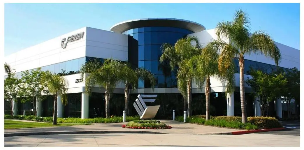
Custom rear-access enclosures demand coordination across structural design, precision sheet metal fabrication, finishing and electromechanical assembly. Distributing those steps across multiple vendors introduces tolerance stack-up risk, schedule exposure and quality accountability gaps. Fabcon removes those handoffs by providing engineering support, laser cutting, CNC punching, forming, welding, finishing and light electromechanical assembly under one roof across 220,000 square feet of manufacturing space in Southern California.
Fabcon’s ISO 9001:2015 and AS9100D certified quality systems govern every stage of the build, providing full traceability from raw material through final assembly, satisfying documentation requirements for data-center infrastructure programs operating under UL, CSA, HIPAA or PCI-DSS frameworks. Agile production cells scale from prototype through mid-volume production without the high minimums or rigid onboarding timelines common among large contract manufacturers. That flexibility supports engineering teams managing evolving bills of materials and compressed program schedules.
Frequently Asked Questions
Minimum Rear Clearance for Hinged Rear Doors
Minimum rear clearance depends on the access mechanism and the installed equipment. Wall-mounted swing-out enclosures require enough standoff from the wall for ventilation, plus additional depth for hot-air exhaust and cable entry behind the swing frame. Freestanding enclosures with single or split rear doors need unobstructed rear aisle clearance for door swing and safe technician access. The deepest installed device, cable bend radius, PDU depth and door thickness all add to the baseline clearance figure. Under-specified rear clearance often drives field modifications and enclosure returns.
Door Style Impact on Airflow
Door style affects airflow through perforation percentage and the integrity of the exhaust path. Perforated rear doors with sufficient open area support front-to-back airflow when aligned with cold-aisle and hot-aisle containment. Solid or glass rear doors trap exhaust heat regardless of door count. Split-door designs can preserve usable perforated area and reduce swing interference. Hinge layout, center meeting line and latch hardware must sit away from fan areas and equipment intake zones. Hinge leaves and reinforcement across perforated regions reduce effective open area and can create localized hot spots.
Compliance Standards for Rear-Access Enclosures
Several standards govern rack enclosure design and installation. EIA-310-D establishes 19-inch mounting width and usable equipment width as fixed dimensions, with depth as the primary variable. ANSI/EIA 310-D-1992 and IEC 60297 define horizontal opening and unit vertical pitch. NFPA 70 sets working space requirements for service aisles. IEC 60529 defines IP ratings for dust and moisture protection. In regulated industries, HIPAA’s Security Rule covers physical safeguards for electronic protected health information, and PCI-DSS Requirement 9.1 mandates limited physical access to systems handling cardholder data. TIA-606 governs cable labeling and administration. Grounding and bonding requirements apply to all powder-coated doors and panels, which need dedicated bonding studs because coating is electrically insulating.
When Custom Rear-Access Enclosures Outperform Standard Products
Off-the-shelf enclosures target the median installation. Custom enclosures fit projects where equipment depth, co-location cage geometry, cooling architecture or compliance documentation requirements fall outside standard product envelopes. AI and GPU server deployments often require enclosures engineered for higher structural loads, nonstandard cable routing paths, rear-door heat-exchanger interfaces and specific bonding and grounding configurations. Custom programs also support DFM collaboration that aligns door style, perforation pattern, hinge placement and cable-management provisions before drawings are released, which reduces rework and field modifications across a production run.
Next Steps for Custom Rear-Access Rack Enclosure Programs
Rear-access design in constrained data-center spaces involves engineering tradeoffs that standard job shops struggle to resolve and large contract manufacturers handle with rigid processes. Door style, clearance geometry, airflow integration, cable routing and compliance documentation work best when resolved together before fabrication begins. Fabcon’s vertically integrated precision sheet metal fabrication and assembly capabilities, combined with ISO 9001:2015 and AS9100D certified quality systems, provide a single accountable U.S. partner for the full program lifecycle from prototype through mid-volume production.