
Key Takeaways
- AI workloads drive rack densities above 100 kW and demand cabinets with stronger structures and higher thermal performance than legacy 42U designs.
- Programs often fail during the transition to production because DFM collaboration starts late, tooling decisions lock in too early and processes lack validation.
- A structured five-phase approach with prototype validation, tooling transition, validation testing, pilot production and production release removes major failure modes before launch.
- Phased tooling, rigorous validation testing and pilot production metrics with high first-pass yield benchmarks support repeatable, high-quality manufacturing at scale.
- Partner with Fabcon for ISO-certified precision sheet metal fabrication and agile production cells that scale custom data center cabinets from prototype to full production.
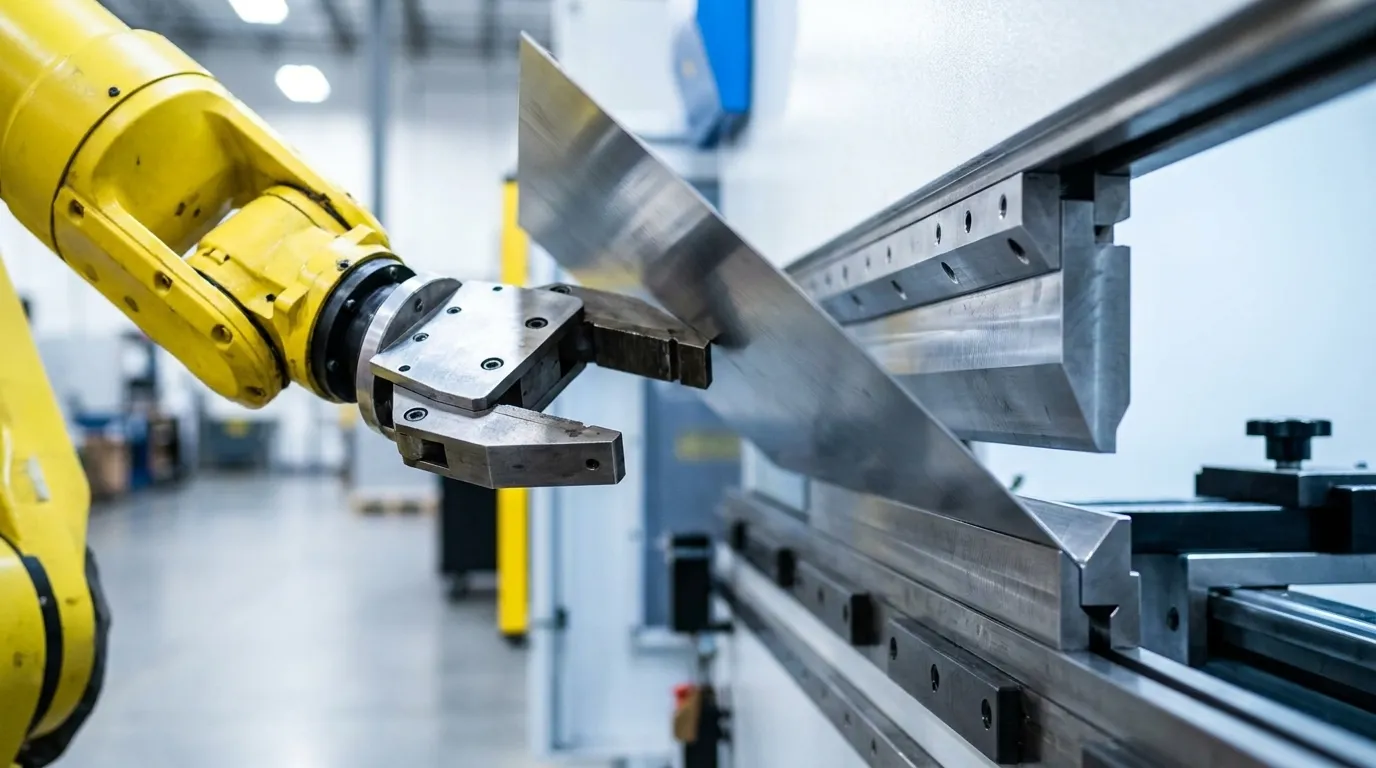
Phase 1: Prototype Validation And DFM Collaboration
DFM works best as a collaboration that begins during prototyping. Early design changes cost less than corrections after first article inspection.
Several DFM principles apply directly to data center cabinet geometry.
- Bend Radii: Minimum inside bend radius should match material grade and thickness. Bending across the grain supports tighter radii in the same material.
- Hole-To-Bend Distance: Keep holes, slots and cutouts clear of bend zones to prevent ovaling and distortion during forming.
- Fastener Standardization: PEM hardware insertion holes need clearance from bend lines so forming does not distort the panel.
- Weld Minimization: Each avoidable weld adds preparation, distortion control, finishing and inspection cost. Tabs, slots, self-locating joints and captive hardware reduce weld count when strength allows.
- Tolerance Stack-Ups: Apply tight tolerances only to functionally critical features. Use ISO 2768-m general tolerances in the title block and tighten only specific dimensions that control fit.
A DFM review checklist for cabinet drawings should confirm key forming and assembly conditions before design freeze. Each check prevents a specific defect that would otherwise appear during production.
- Inside bend radius matches material grade and thickness
- Holes and cutouts stay clear of bend zones
- Bend relief appears at all intersecting flanges
- Material thickness remains uniform across the part
- PEM hardware locations avoid forming operations
- Welds stay minimized and accessible for inspection
- Tight tolerances apply only to functional interfaces
Phase 2: Tooling Transition From Soft To Hard
Tooling decisions based on early optimism create some of the most expensive mistakes in the prototype-to-production transition. A clear view of the tooling spectrum supports better capital planning.
Soft tooling includes CNC laser cutting, turret punching and press brake forming with standard tooling. It carries low NRE cost, supports rapid design iteration and fits programs with evolving designs or uncertain volumes.
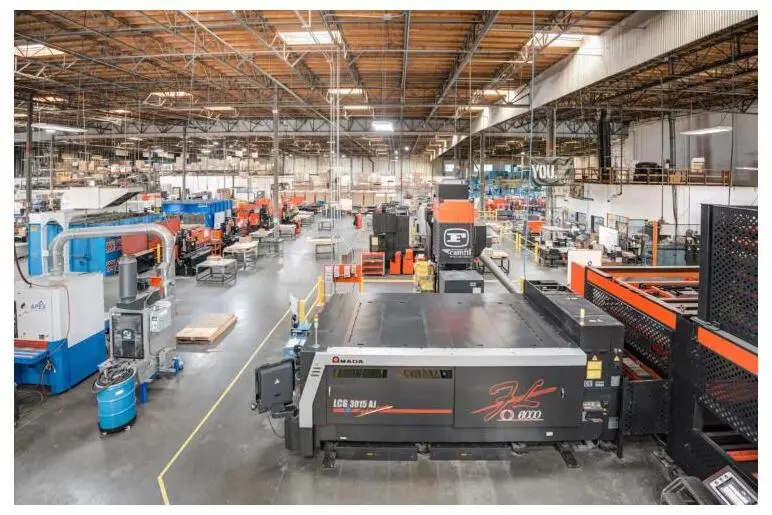
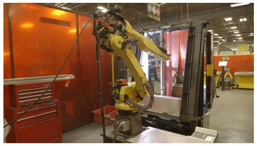
Hard tooling uses dedicated dies, fixtures and automated robotic welding cells. It requires meaningful NRE investment but lowers per-unit cost and improves process capability. Hard tooling achieves higher Cpk values than soft tooling, which matters for tight dimensional requirements across long production runs.
The crossover between soft and hard tooling depends on part complexity, program duration and design stability. Design changes after cutting hard tooling cost far more than changes during soft-tooled builds.
Common tooling options in cabinet manufacturing include the following.
- CNC laser cutting for prototypes, complex geometries and low-to-mid volume
- CNC turret punching for mid-volume production and repetitive hole patterns
- Press brake forming with standard tooling for flexible bend geometries at any volume
- Dedicated forming dies for high-volume programs with stable geometries
- Automated robotic welding cells for production scaling and repeatable weld quality
Phased tooling commitment reduces risk. Programs start with soft tooling, validate the design through pilot production and transition to hard tooling when validated volume supports the NRE investment.
Phase 3: Validation Testing And Compliance
Validation testing works best as a phased process that informs design and manufacturing decisions at each stage. Mapping tests to the correct phase reduces late redesigns and compliance failures.
Key validation tests for data center cabinets include several structural, thermal and usability checks.
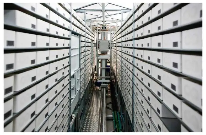
- Static Load Testing: Static load testing verifies that the cabinet structure supports rated equipment weight without permanent deformation.
- Seismic Testing: Telcordia GR-63-CORE Zone 4 requirements specify that cabinets must survive specified acceleration with a defined payload without tipping, moving more than 1 inch or ejecting hardware. A GR-63-CORE test report at RFQ stage provides stronger evidence than marketing claims.
- Thermal And Airflow Validation: ASHRAE TC 9.9 guidelines define inlet temperature envelopes for A1 class, with door perforation of at least 60 percent open area recommended for racks up to 8 kW, rising to 70–80 percent for 10–30 kW loads.
- Serviceability Testing: Doors, side panels and cable management systems should function correctly through repeated use cycles.
Several industry standards govern cabinet design and compliance.
- EIA-310-E defines the 19-inch mounting width, rack unit height and common cabinet heights such as 42U, 45U and 48U.
- Telcordia GR-63-CORE covers physical protection, environmental conditions and mechanical dynamics for telecom and data center infrastructure and often pairs with GR-1089-CORE for EMC compliance.
- ASHRAE TC 9.9 thermal guidelines define server inlet temperature and humidity ranges at the cabinet inlet.
- UL 2416 covers structural integrity, fire-escape compliance and grounding standards for IT hardware and enclosures across North America.
ISO 9001:2015 and AS9100D certified quality systems provide full part traceability, which supports compliance in infrastructure-critical deployments. Fabcon holds both certifications and supplies the documentation backbone that engineering and procurement teams need for regulatory signoff.
Get a quote and discuss validation testing requirements with Fabcon’s engineering team.
Phase 4: Pilot Production And Process Freeze
A pilot run produces a small batch that validates the production process. Earlier phases already addressed product design, so this phase focuses on assembly line setup, operator execution, test fixture performance and QC checkpoint effectiveness.
Several metrics provide insight during the pilot run.
- First-Pass Yield: Healthy benchmarks exceed 95 percent before rework. Defects clustered at a single assembly step become major bottlenecks when volume increases.
- Dimensional Accuracy: Production units should match prototype measurements based on CMM or equivalent inspection methods.
- Defect Clustering: Mapping defects by assembly step highlights process constraints before volume ramp.
Go and no-go criteria should be defined before reviewing pilot data. Criteria set after seeing the numbers lose objectivity and weaken the gate.
Design freeze should remain in force at the start of pilot production. Engineering changes during this phase invalidate process validation and require a new pilot. Any change that cannot wait for the next phase should trigger formal change control with updated documentation.
Phase 5: Production Release And Supply Chain Integration
A complete production release package reduces ambiguity on the manufacturing floor and protects program continuity across production runs. The package should include the core documents and records that define the build.
- Final bill of materials with approved vendor list
- Detailed drawings with controlled tolerances
- Work instructions for fabrication, finishing and assembly
- Traceability records linking every part to its material lot
- Inspection and test reports
Vertical integration creates a structural advantage at this phase. A manufacturing partner that manages fabrication, finishing and light electromechanical assembly under one roof removes vendor handoffs, reduces supplier complexity and shortens lead times.
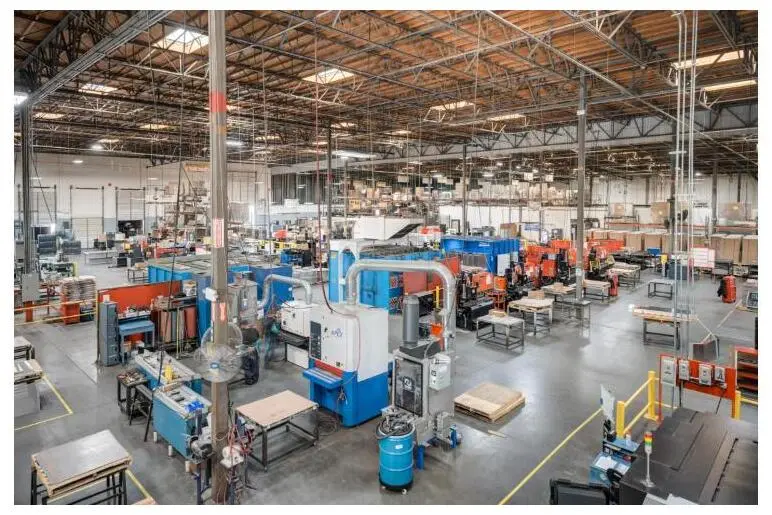
Fabcon’s agile production cells adapt to changing volumes and evolving BOMs without the high minimums and rigid onboarding requirements of large contract manufacturers. Programs that begin at prototype scale can ramp to production with the same partner and maintain a consistent qualification path.
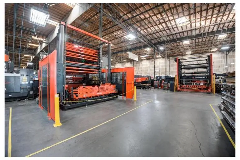
Even with a complete release package, programs can stumble when design and manufacturing lose alignment. Cross-phase coordination keeps teams synchronized as requirements evolve.
Cross-Phase Coordination Risks To Watch
Design-To-Manufacturing Disconnect: Features that measure correctly after cutting can shift after bending or welding. Powder coating can close a slot or affect a grounding point. Early DFM collaboration with the manufacturing partner aligns drawings, processes and finishing steps.
Weld Distortion Management: Welding introduces heat that distorts thin-gauge cabinet panels. Thoughtful joint design, reduced weld count, automated robotic welding and balanced weld sequencing control distortion across the assembly.
Tooling Commitment And Demand Alignment: Tooling for forecasted volume that never materializes ties up capital. Phased tooling that tracks validated demand keeps NRE aligned with real program performance.
Communication Between Design And Manufacturing: Clear drawings specify weld type, size and length per AWS standards. Practical datums support inspection. Notes state whether dimensions are checked before or after finishing.
Conclusion And Next Steps
The prototype-to-production journey for custom data center cabinets works best as five sequential phases: DFM collaboration, tooling transition, validation testing, pilot production and production release. Each phase builds capability and reduces risk for the next stage.
The global data center rack market continues to grow as AI density reshapes structural, thermal and dimensional requirements for cabinet enclosures. Programs that manage the transition with discipline can scale with that demand and support future hardware generations.
Fabcon brings 45-plus years of precision sheet metal fabrication experience to data center infrastructure programs. Its ISO 9001:2015 and AS9100D certified quality systems, vertically integrated fabrication, finishing and light electromechanical assembly and agile production cells support a smooth prototype-to-production transition.
Get a quote from Fabcon’s engineering team for a DFM review of a data center cabinet design.
Frequently Asked Questions
What Is The Difference Between Soft Tooling And Hard Tooling For Data Center Cabinets?
Soft tooling uses standard CNC laser cutting, turret punching and press brake forming with off-the-shelf tooling. It requires little upfront NRE investment and supports rapid design changes, which suits prototypes and early production runs with evolving designs. Hard tooling uses dedicated dies, fixtures and automated robotic welding cells built for a specific geometry. It lowers per-unit cost and improves process capability across high-volume runs but requires significant NRE and makes design changes expensive. Validated volume, design stability and program duration should drive the transition from soft to hard tooling. Phased commitment that starts with soft tooling and transitions when volume supports it reduces risk.
Why Do Data Center Cabinet Programs Fail During The Prototype-To-Production Transition?
Common failure modes include design-to-manufacturing disconnect, tolerance stack-up issues, weld distortion and premature tooling commitment. A design that works as a hand-built prototype can fail at volume because manual tolerance control does not transfer to high-speed production processes. Weld distortion that a technician corrects in a prototype becomes a systematic defect in production. Tolerance stack-ups that pass individual part inspection can cause assembly failures when variation accumulates across multiple components. Early DFM collaboration with a manufacturing partner before design freeze surfaces and resolves these issues before they reach production.
What Industry Standards Govern Data Center Cabinet Design And Validation?
Several standards define dimensional, structural and environmental requirements for data center cabinets. EIA-310-E establishes the 19-inch mounting width and rack unit dimensions that govern mounting interface compatibility. Telcordia GR-63-CORE defines seismic requirements, including Zone 4 specifications for acceleration, payload and hardware retention. ASHRAE TC 9.9 provides thermal guidelines for inlet temperature envelopes and door perforation requirements at various rack power densities. UL 2416 covers structural integrity, fire-escape compliance and grounding standards for IT enclosures in North America. ISO 9001:2015 and AS9100D certified quality systems provide the traceability and documentation framework required for compliance in infrastructure-critical deployments. Programs that map validation testing to these standards during DFM review allow test requirements to guide design decisions.
How Does AI-Driven Rack Density Affect Cabinet Manufacturing Requirements?
AI workloads concentrate more compute and power into each rack than conventional enterprise servers. Average rack densities have risen, and high-performance AI deployments plan around rack power levels that exceed traditional air-cooled cabinet specifications. This shift drives several manufacturing requirements. Cabinets need reinforced structural frames with higher static and dynamic load ratings. Greater cabinet depth and height support larger equipment footprints. Liquid-cooling-ready designs with manifold interfaces and quick disconnects become more common. Higher door perforation percentages improve thermal management. Cabinet programs that target AI deployments benefit from designing for these requirements at the prototype phase because early structural and thermal decisions determine long-term capability.
What Should A Production Release Package Include For A Custom Data Center Cabinet?
A complete production release package removes ambiguity on the manufacturing floor and protects continuity across production runs. It should include a final bill of materials with an approved vendor list, detailed drawings with controlled tolerances, work instructions for fabrication, finishing and assembly, traceability records that link every part to its material lot and inspection and test reports from pilot production. The package should reach a stable state before production begins. Changes after release require formal change control and may affect process validation. A vertically integrated manufacturing partner can maintain this documentation across the full build, from raw material through finished assembly, and provide the traceability that infrastructure-critical programs require.