DFM Guidelines for Sheet Metal Product Development
Last updated: August 11, 2026
Key Takeaways for Sheet Metal DFM
DFM guidelines for sheet metal product development cover material selection, bend geometry, hole placement, tolerance strategy and assembly features for consistent fabrication at scale.
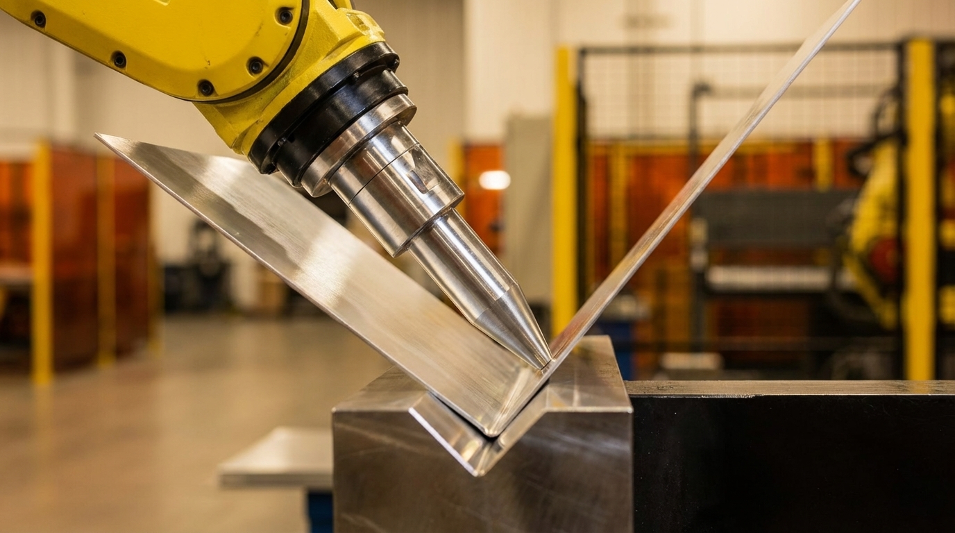
Standard material gauges and bend radii that match common shop inventory cut tooling cost, shorten lead times and reduce distortion or cracking during forming.
Minimum hole-to-bend distances, flange lengths and bend-relief rules prevent distortion, tearing and angle drift in formed parts.
A 12-step CAD review sequence plus single-datum dimensioning controls tolerance stack-up across multiple bends and preserves laser-cut accuracy on critical features.
These eight rules translate directly into CAD decisions that improve manufacturability. Each rule includes a reference table and a short worked example.
1. Standardize Material and Thickness to Avoid Extra Tooling
Standard gauges that match common shop inventory reduce material cost, tooling changes and lead times for production runs.
The following table summarizes four core standardization rules that prevent tooling delays and complexity.
Worked example: A chassis design originally specified three thicknesses. Consolidating to standard gauges reduced material SKUs, brake setups and nest programs while maintaining structural performance.
Troubleshooting: distortion near bends Distortion near bends often traces back to non-standard or inconsistent gauge within the same flat pattern. When material thickness varies across a part, the K-factor and bend allowance calculations change from region to region. That variation produces flanges that sit out of plane after forming. Standardizing to a single gauge per part aligns bend calculations and removes this distortion source before the first piece is cut.
Minimum flange length rules follow the same logic. Flange lengths below 3.5T increase the risk of angle drift and tool marking in standard press-brake air bending. Bend relief width and depth must scale with material thickness and inside radius to prevent tearing at intersecting bends.
3. Hole, Slot and Edge Distances Around Bends
Holes placed too close to a bend line distort during forming because material in the bend zone flows plastically. A standard hole-to-bend distance keeps features outside this deformation zone.
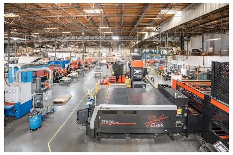
Precision starts at the cut. In-house laser cutting delivers tight-tolerance blanks with the speed and repeatability that high-mix, infrastructure-grade programs demand.
Orient long axis parallel to bend line where possible
Reduces stress concentration at slot ends
Worked example: A steel panel has a 0.060 in inside radius. The minimum hole-to-bend distance is 2.5 times thickness plus radius. A mounting hole placed inside that zone elongated during forming. Moving it farther from the bend resolved the issue without changing the overall envelope.
4. 12-Step CAD Review Sequence for Sheet Metal
A structured CAD review catches DFM issues before release. Running checks in sequence prevents small problems from compounding into major rework.
Step
Check
Common Finding
1
Confirm material and gauge against standard stock
Non-standard thickness specified
2
Verify inside bend radius meets material minimum
Radius too tight for alloy
3
Check all flange lengths meet minimum
Short return flanges on enclosure lips
4
Confirm bend relief at every open-corner bend
Missing relief on intersecting bends
5
Measure hole and slot to bend distances
Mounting holes inside minimum zone
6
Identify datum surfaces and reference all critical dimensions from them
Chain dimensioning across bends
7
Review tolerance callouts for stack-up risk
Unnecessarily tight tolerances on non-critical features
8
Check for self-locating tab-and-slot features
No locating geometry, relies on welder judgment
9
Confirm hardware standardization, fastener types and sizes
Mixed metric and imperial fasteners
10
Account for finish thickness on mating surfaces
Coating thickness not subtracted from slip joints
11
Verify flat-pattern bend allowance and K-factor
Default K-factor used for alloy
12
Confirm grain direction for aluminum bends
Bend parallel to grain on alloy
Worked example: A data center chassis passed internal review but failed Step 10. Electrostatic powder coating adds thickness per side, which closed the clearance on a slide-in card guide. Subtracting the finish allowance in CAD before fabrication avoided a rework cycle after finishing.
In-house finishing — powder coat, wet paint, silkscreen, and CARC mil-spec coating — keeps cosmetic standards consistent and removes a supplier handoff from the build.
Worked example: An enclosure with four bends had connector cutouts dimensioned chain-style from flange to flange. Redimensioning all cutouts from a single primary datum on the base flat reduced the tolerance stack-up on bends to the laser-cut accuracy of the flat blank.
Sheet metal design for manufacturability also covers how parts assemble. Self-locating features reduce fixture cost, assembly time and tolerance stack-up across multi-part builds.
A U.S.-based partner since 1977 — Fabcon combines the infrastructure of a large contract manufacturer with the responsiveness and made-in-America accountability of a specialist.
Tab-and-slot features suit 90-degree joints in material up to 6 mm thick and assemblies that remain permanent. They add less value for non-90-degree joints, thick plate, assemblies that require future disassembly or one-off prototypes where extra design time does not pay back.
Downloadable DFM Checklist for Sheet Metal Product Development
This checklist supports final review before releasing any sheet metal drawing for fabrication. Each item maps to a rule section above.
Material and gauge confirmed against standard stock
Inside bend radius meets material-specific minimum (1T default, 3T–4T for 6061-T6)
All flange lengths at least 4T or 3 mm, whichever is greater
Bend relief present at every open-corner bend (at least 1T wide by 1T plus R deep)
All holes and slots at least 2.5T plus R from nearest bend line
12-step CAD review sequence completed and signed off
Critical dimensions referenced from a single common datum, not chained bend-to-bend
General tolerance set to ISO 2768-m, tighter callouts applied only to critical features
Self-locating tab-and-slot features included where welded or fastened joints occur
Finish thickness subtracted from mating slot and slip-joint dimensions in CAD
Grain direction confirmed for all aluminum bends
First article inspection planned for all critical dimensions before full production release
Conclusion: Turning Sheet Metal DFM Rules into Reliable Production
Applying these DFM guidelines before drawing release prevents distortion, tolerance stack-up and vendor handoff delays that drive rework and missed launch dates. Each rule in this checklist maps to clear CAD parameters that fabricators can act on from the first prototype.
Fabcon’s vertically integrated facilities cover fabrication, finishing and light electromechanical assembly under one roof, with certified quality systems governing every stage. Engineering and quoting teams review drawings together before production begins so DFM issues resolve at the drawing stage rather than on the floor.
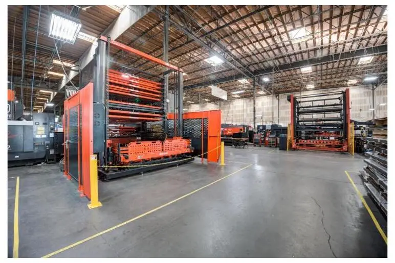
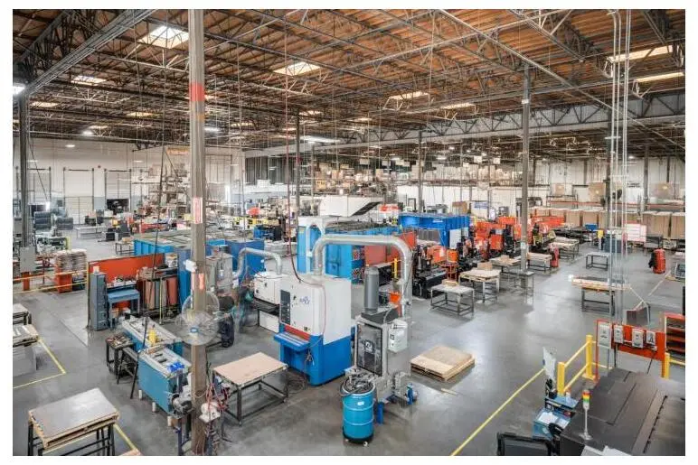
Founded in 1977, Fabcon runs 220,000 sq ft of vertically integrated fabrication across two Southern California facilities — engineering, machining, fabrication, finishing, and assembly under one roof.
Most impactful DFM rule for sheet metal product development
Tolerance strategy creates the most costly errors. Designers who chain dimensions bend-to-bend instead of referencing a single datum allow small angular errors to accumulate across the part. A critical mounting hole that meets spec at every individual bend can still miss its target position when four or five bends contribute variation. A master datum and cutting critical holes before bending preserve laser-cut accuracy and remove a leading cause of failed first articles.
Best timing for DFM review in product development
DFM review delivers the most value before drawing release for fabrication, during detailed design when geometry is set but before tooling or production planning begins. Changes made at the drawing stage cost a fraction of changes made after first articles. For NPI programs, involving the fabricator during design review rather than at the quoting stage compresses the feedback loop and reduces revision cycles. Fabcon’s engineering and quoting teams review drawings together at the start of every program to surface DFM issues before production begins.
How material selection shapes bend radius and flange length
Material selection sets the minimum inside bend radius, which then defines the minimum flange length. Mild cold-rolled steel is the most forgiving alloy and supports tight radii with short flanges. Stainless steel work-hardens during bending, which requires a larger minimum radius and more force. 5052-H32 aluminum is the preferred choice when tight bends are needed. 6061-T6 aluminum has low ductility in the T6 temper and needs a substantially larger minimum radius than other common alloys. Specifying 6061-T6 where 5052-H32 would perform equally well increases scrap risk and can require forming in an annealed temper followed by heat treatment.
Self-locating features that reduce assembly time and handoffs
Tab-and-slot geometry is an effective self-locating feature for welded and fastened sheet metal assemblies. Tabs cut on one part fit into matching slots on the mating part and hold position before and during welding without external fixtures. This approach reduces assembly time, lowers the skill level required for consistent positioning and limits cumulative tolerance stack-up across multi-part builds. Formed flanges can also act as built-in locators that establish alignment before fastening. Standardizing fastener types and sizes across an assembly further reduces BOM complexity and prevents assembly errors from mixing fastener standards. For electromechanical enclosures, these features support fabrication, assembly and finishing under one roof without vendor handoffs.
Fabcon support for prototype-to-production sheet metal programs
Fabcon supports programs from initial prototype through mid-volume production runs from two Southern California facilities totaling 220,000 square feet of vertically integrated manufacturing space. In-house capabilities span laser cutting, CNC punching, forming, welding, CNC machining, powder coating, wet paint, mil-spec finishing and light electromechanical assembly. Because all of these processes operate under one roof, programs do not require separate vendors for fabrication, finishing and assembly. Fabcon’s agile production cells adapt to changing volumes and evolving bills of materials without the high minimums or long onboarding timelines associated with large contract manufacturers. ISO 9001:2015 and AS9100D certified quality systems provide full traceability from prototype through production.