Best Practices for Designing Sheet Metal Parts for DFM
Last updated: August 10, 2026
Key DFM Rules for Sheet Metal Parts
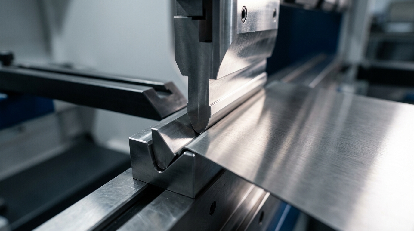
Four core DFM rules for bend radii, flange lengths, hole-to-bend clearance and bend relief prevent cracking, distortion and tolerance drift.
Material selection and consistent gauge across a part family set forming limits and reduce tooling changes.
Violating hole-to-bend or bend-relief rules often forces secondary operations and first-article rejections that raise cost and extend lead time.
Defining a primary datum early and orienting critical bends across the grain controls tolerance stack-up and cracking risk on multi-bend parts.
Early collaboration with Fabcon embeds DFM feedback before release and shortens launch timelines on mid-volume programs.
1. Material and Thickness Selection
Choose formability first. Material choice sets every downstream forming limit. Mild steel and 5052-H32 aluminum provide wide process windows. 6061-T6 aluminum and work-hardening stainless grades such as 304 need larger radii and tighter process control.
Standardize gauge across a part family. Mixing gauges within a program multiplies tooling setups and increases scheduling complexity because each thickness change requires a different die setup and process window. Consistent thickness across related parts removes those transitions, reduces tool changes and keeps forming predictable.
Cost and lead-time tie-in: DFM-aware designs shorten quoting time because the manufacturing engineer does not need to hunt for and flag problematic features.
Plan for the effect of insufficient clearance. Holes placed within the bend deformation zone can ovalize and shift position, which creates fastener seating issues and assembly mismatch. Corrective actions often involve moving the hole, adding bend relief or creating the hole as a secondary post-form operation. Each step adds time and cost.
Cost and lead-time tie-in: First-article rejections caused by missing bend relief often require re-cutting, re-forming and re-inspecting the part. That sequence can add days to a program and consume engineering bandwidth that could support design iteration.
5. Tolerance Strategy Across Multiple Bends
Multi-bend parts introduce cumulative variation because each bend adds a small positional error. Without a clear tolerance strategy, the final features can drift far from nominal even when each bend stays within spec.
Cost and lead-time tie-in: Grain-direction issues discovered at first article often require a material re-orientation, which changes the flat-pattern nesting and may increase scrap. In other cases, a radius increase alters the developed blank length and downstream fit-up dimensions.
7. Finishing and Drainage Requirements that Protect Fit and Coating
Account for coating thickness in clearance fits.Electrostatic powder coating adds a polymer layer of 60 to 120 microns per side. On slip joints or hinges, that added thickness can convert a designed clearance fit into an interference fit and cause binding during assembly. Design teams should subtract coating thickness from CAD clearances so the model reflects the finished, coated state.
Add drainage holes to enclosed pockets. Liquid finishing processes trap solution in blind pockets, which causes adhesion failures and corrosion. A drainage hole at the lowest point of each enclosed feature allows solution to exit cleanly.
Cost and lead-time tie-in: Finishing rework such as stripping, re-coating and re-inspecting ranks among the most time-consuming secondary operations in a fabrication program. Designing for drainage and coating thickness removes the root cause before the part reaches the finishing line.
8. Verification Steps Before Release
Final verification connects the DFM rules above to daily release practice and prevents late-stage surprises. A short checklist keeps each drawing aligned with shop capability.
Run a DFM checklist against every released drawing. Before releasing a drawing to fabrication, verify the following:
All inside bend radii meet material-specific minimums
All flange lengths meet the 4T minimum for standard tooling
All holes maintain the required clearance from bend lines
Bend relief features are present at every exposed corner and partial bend
Tolerances are assigned by function, not default, and a primary datum is defined
Critical bends are oriented perpendicular to the rolling grain
Clearance fits account for coating thickness
Hardware insertion sequence is specified before finishing
Key DFM parameters include inside bend radius, minimum flange length, hole-to-bend clearance and bend relief width. These values vary by material and thickness. A qualified fabricator can provide the specific limits that apply to each part family.
Collaborate Early with a Vertically Integrated Fabricator
The rules above prevent the most common failure modes in sheet metal design. A deeper challenge often remains, which is the design-to-manufacture disconnect that appears when engineering and fabrication operate in isolation.
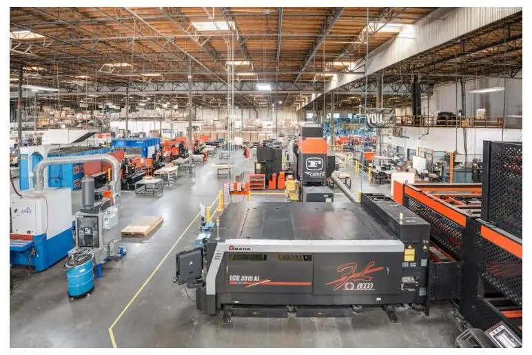
Precision starts at the cut. In-house laser cutting delivers tight-tolerance blanks with the speed and repeatability that high-mix, infrastructure-grade programs demand.
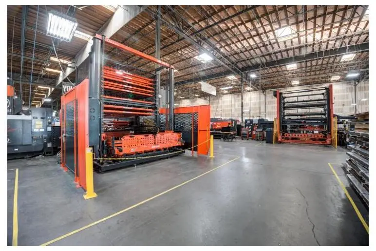
Fabcon is a vertically integrated U.S. precision sheet metal fabrication and assembly partner. Operating from 220,000 square feet across two Southern California facilities, Fabcon manages fabrication, finishing and light electromechanical assembly under one roof. Engineering and quoting teams review drawings, tolerances and materials before production begins and catch DFM issues at the lowest cost point.
In-house finishing — powder coat, wet paint, silkscreen, and CARC mil-spec coating — keeps cosmetic standards consistent and removes a supplier handoff from the build.
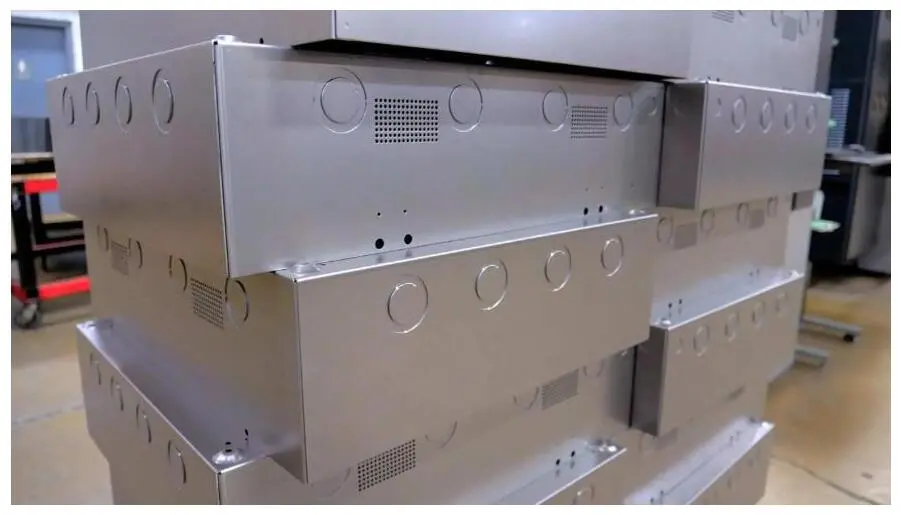
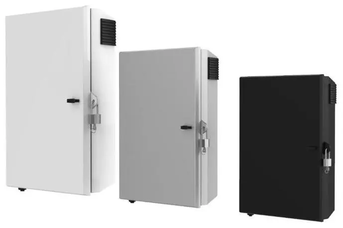
Precision metal enclosures with tight, clean bends and consistent finishing — produced to ISO 9001:2015 and AS9100D standards with full traceability on every part.
Early collaboration with Fabcon’s engineering team brings DFM feedback into the program before drawings reach release. That timing shift removes many rework cycles, quoting delays and vendor handoff gaps that raise cost and compress launch timelines on mid-volume, high-mix programs.
Weatherproof, customizable enclosures with electromechanical integration for energy storage and power distribution — engineered for commercial and public deployments.
Get a quote and connect with Fabcon’s engineering team before the next design release.
Modular, rack-mounted enclosures and structural systems that simplify cooling, cable management, and integration for hyperscale and edge data-center deployments.
Frequently Asked Questions
What is the most common DFM mistake in sheet metal design?
The most common mistake is specifying bend radii below the material-specific minimum, particularly on aluminum alloys in hard tempers. This choice forces the fabricator to coin the part rather than air-bend it, which increases tooling wear, cycle time and cost. A second frequent error is placing holes too close to bend lines, which causes ovalization during forming and creates fastener seating problems in final assembly.
How does tolerance stack-up affect multi-bend enclosures?
Each bend introduces a small angular and positional variation. On parts with many consecutive bends, those variations accumulate so the final feature, such as a mounting hole pattern or mating flange, can drift significantly from nominal even when every individual bend stays within its local tolerance. The mitigation is to define a primary datum early, reference all subsequent features to that datum rather than to the previous flange and apply GD&T callouts that reflect the functional requirement of the final assembly.
When should a design use welded subassemblies instead of a single formed part?
Welded subassemblies become the better choice when a single formed part would require many consecutive bends, deep returns close to bend lines or tight offsets clustered in a small area. In those cases, forming simple, accurate subcomponents with one or two bends each and then fixturing and welding them together allows critical dimensions to be set during assembly rather than accumulated through a long bend sequence. The welded approach can achieve tighter final fits than a single complex forming operation.
How does powder coating affect part fit-up, and when should it be accounted for in the design?
Powder coating adds a measurable polymer layer to all coated surfaces. On slip joints, hinges and mating flanges, that added thickness can convert a designed clearance fit into an interference fit. The coating thickness should be subtracted from CAD clearances before release. Self-clinching hardware should also be installed before finishing, not after, to preserve clinch strength and prevent finish cracking around the hardware seat.
What are the advantages of working with a vertically integrated fabricator versus managing separate vendors for fabrication, finishing and assembly?
A vertically integrated fabricator removes the inter-facility transportation, double handling and scheduling gaps that occur when parts move between separate vendors. Quality accountability stays with one partner across the entire build, which reduces the finger-pointing that fragmented supply chains produce when a defect appears late. DFM feedback becomes faster and more actionable because the engineering, fabrication, finishing and assembly teams share the same facility and the same program context. For mid-volume, high-mix programs, that integration compresses lead times and reduces the administrative overhead of managing multiple purchase orders and vendor relationships.
Does grain direction matter for all sheet metal materials, or only specific alloys?
Grain direction matters for all rolled sheet metal, but its impact is strongest in low-ductility alloys. For mild steel and 5052-H32 aluminum, bending perpendicular to the grain allows tighter radii with lower cracking risk, while bending parallel to the grain often remains acceptable at standard radii. For 6061-T6 and 7075-T6 aluminum, the effect is pronounced enough that bending parallel to the grain at minimum radii becomes a reliable cause of first-article cracking. On structural or cosmetic parts in these alloys, orienting critical bends perpendicular to the rolling direction is standard practice.
Conclusion
Four rules guide sheet metal DFM. Set material-appropriate bend radii, maintain minimum flange lengths, keep holes clear of bend zones and add bend relief at every exposed corner and partial bend. Applying these rules during design prevents the cracking, distortion and tolerance drift that generate rework, delay quoting and raise program cost.
The rules form a strong base but do not replace collaboration. The design-to-manufacture disconnect, the gap between what engineering releases and what a fabricator can build efficiently, calls for early partnership with a supplier that owns the entire build. Fabcon’s integrated engineering, fabrication, finishing and assembly capabilities, backed by ISO 9001:2015 and AS9100D certification, address that gap from the first design review through final shipment. The earlier collaboration section describes how this approach brings DFM expertise into the program before drawings reach release and keeps launches on schedule.
Get a quote from Fabcon and align sheet metal designs with proven DFM practice from day one.