
Last updated: August 15, 2026
Key Takeaways
- Sheet metal enclosure DFM guidelines cover material selection, bend radii, hole placement, flange lengths, hardware and tolerances for repeatable fabrication under ISO 9001:2015 and AS9100D.
- Standardizing on one alloy and one thickness per program reduces tooling changes, simplifies procurement and keeps flat-pattern calculations consistent across production runs.
- Practical rules for bend radii, flange lengths, bend relief, hole-to-bend distances and captive hardware prevent distortion, tearing and costly rework during forming and assembly.
- Early DFM collaboration and realistic tolerances under these quality standards catch conflicts before release, reduce lead times and support U.S. reshoring goals.
- Partner with Fabcon for integrated fabrication, finishing and assembly under one roof to eliminate vendor hand-offs and accelerate prototype-to-production transfer.
Core DFM Rules at a Glance
These rules guide material selection, bend radii, hole placement, flange lengths, hardware and tolerances. The goal is repeatable fabrication, finishing and assembly under ISO 9001:2015 and AS9100D. Applying these rules reduces rework and shortens lead times.
1. Material and Thickness Selection for Enclosures
Material choice drives every downstream decision in enclosure design. Cold-rolled steel and 5052-H32 aluminum serve as workhorses for U.S. enclosure programs because domestic availability is reliable and both alloys form predictably across common gauges.
Standardizing to one alloy and one thickness per program reduces tooling changes, simplifies procurement and keeps flat-pattern calculations consistent. Mixing gauges within a single enclosure introduces springback variation that compounds across bends.
Domestic production reduces dependence on long international supply chains that tariffs and logistics disruptions can interrupt. U.S.-available alloys therefore support both technical performance and supply-chain resilience, especially for programs with complex fabrication, frequent engineering changes or high transportation costs.
2. Inside Bend Radius by Alloy and Temper
A practical default inside bend radius of 1T covers most mild steel, stainless and formable aluminum in common enclosure gauges. Harder tempers or thicker stock need 1.5T to 2T or larger to avoid cracking.
This default must be adjusted for temper, thickness and grain direction rather than treated as a universal number. Bending across the grain allows tighter radii than bending with the grain and reduces the risk of cracking along the grain.
6061 in the T6 temper illustrates why these adjustments matter. Its low ductility in T6 makes tight bends risky, so many programs form 6061 in O or T4 temper and then age afterward when tight radii are required.
Using a single consistent inside radius across an entire enclosure part allows the shop to form every bend with the same punch and die. That consistency reduces tooling changes, setup time and overall cost.
3. Minimum Flange Length for Stable Forming
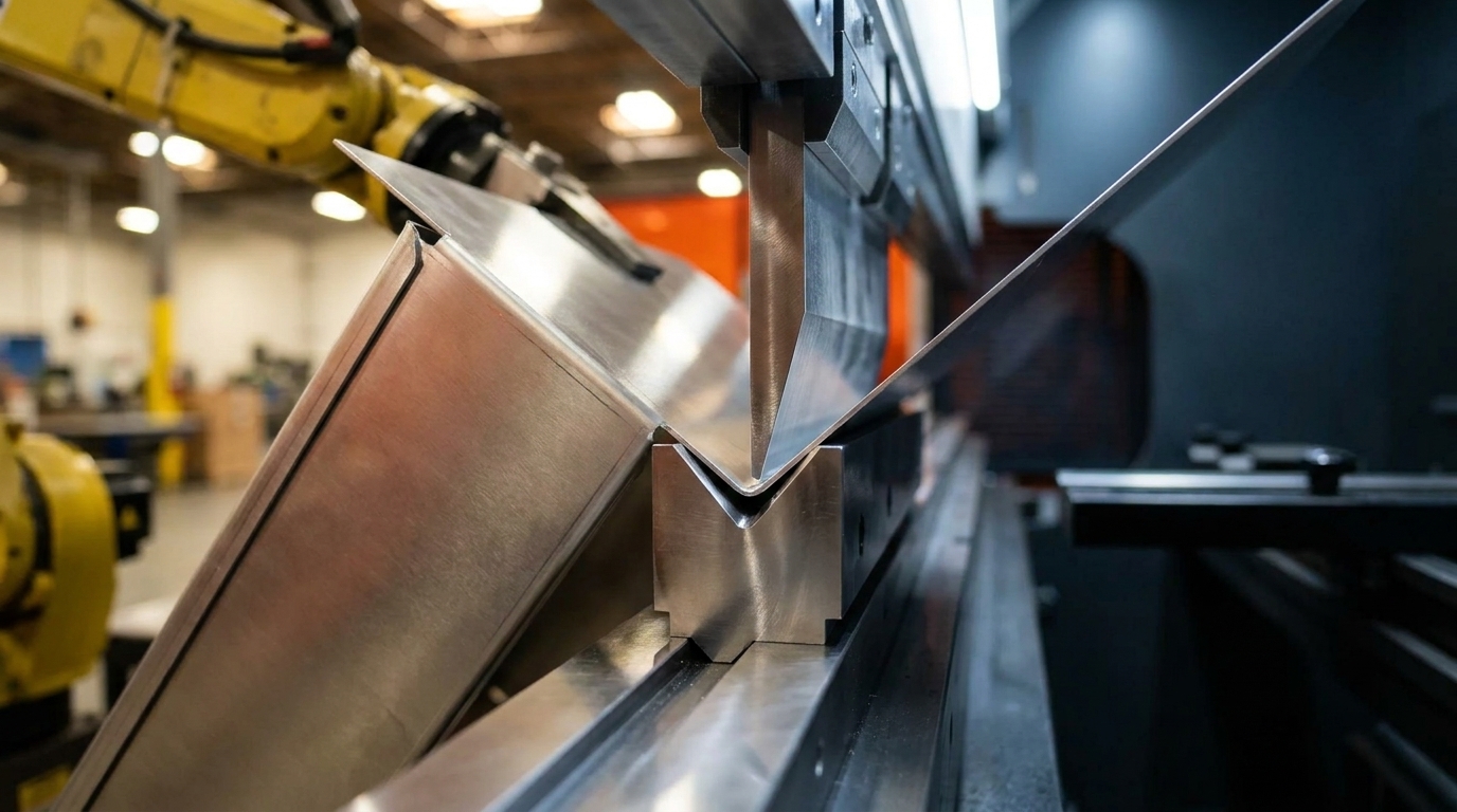
A practical minimum flange length for sheet metal parts is roughly 4T. A flange shorter than about half the V-die opening plus the radius can slip into the die during brake forming, which produces an inconsistent bend angle and a scrap part.
Targeting 6T or greater gives the press brake operator reliable material support and reduces the chance of die slip across production runs. Short flanges that appear acceptable in CAD often fail at the machine once material springback enters the picture.
4. Bend Relief Dimensions That Prevent Tearing
Bend relief cuts at notch ends should have a width of at least 1T to prevent tearing at the corners during forming. Increasing that width to 1.5T with radiused corners further reduces stress concentration, particularly in stainless steel and harder aluminum tempers.
Relief depth must clear the full bend deformation zone. A relief that is too shallow transfers forming stress into the adjacent flat, which distorts nearby holes and mating surfaces. Reviewing bend relief geometry in the flat pattern before release catches this class of error before it reaches the floor.
5. Hole-to-Bend and Hole-to-Edge Distances That Protect Features
The minimum distance from a hole edge to the bend line is 2T plus R for holes smaller than roughly 1 inch in diameter, where T is material thickness and R is the inside bend radius. This spacing prevents distortion during forming in steel, aluminum and stainless enclosure parts.
For larger holes and slots, the minimum hole-to-bend distance increases to 2.5T plus R. When R equals T, these formulas simplify to roughly 3T and 3.5T, which provides a quick mental check during early layout.
Recommended minimum hole-to-edge distance is 2T from hole edge to part edge for punched holes to prevent bulge or tear-out. Threaded or extruded holes near edges need 2T to 3T clearance because they concentrate more load and draw material during forming.
6. Captive Hardware Choices That Match Sheet Metal Design
Self-clinching fasteners install into sheet metal through cold flow of parent material into the fastener groove. This process provides permanent full-strength threads without tapping or welding and often replaces tapped holes in thin-gauge panels.
Hardware selection must match the sheet material and manufacturer guidance. For self-clinching fasteners in stainless or softer materials, select the hardware family for that sheet alloy and use manufacturer-specified hole diameters rather than nominal thread size to achieve proper clinch retention.
Installation sequence also affects quality. Self-clinching hardware must be installed after punching and forming but before painting or plating, because mechanical deformation would crack any pre-applied finish. Drawings should specify the PEM part number, installation side and a note to install per PEM specifications.
Floating fasteners merit consideration when the assembly needs misalignment tolerance. They accommodate stack-up tolerances between mating panels in multi-bolt patterns and reduce cross-threading during assembly.
Regardless of hardware type, edge distance remains non-negotiable. A minimum edge distance of 2 times the hole diameter must be maintained when installing self-clinching hardware to prevent sheet buckling or deformation during pressing and in service.
7. Bend Sequence and Flat-Pattern Verification Before Release
Bend order determines whether a part can be formed at all. A sequence that appears logical in 3D CAD can trap the brake tooling on a later bend and make the part impossible to complete without redesign.
K-factor values for bending typically range from 0.33 to 0.40 for aluminum, 0.40 to 0.45 for mild steel and about 0.45 for stainless steel. Applying the correct K-factor per alloy in the flat-pattern calculation keeps developed lengths aligned with the formed part and prevents cumulative dimensional error across multiple bends.
Verifying the flat pattern in CAD before release and reviewing the bend sequence with the fabricator catches tooling-access conflicts early. This review is especially important for U-channel and box-form enclosures where interior bends close off access for subsequent operations.
8. Realistic Tolerances Under Established Quality Standards
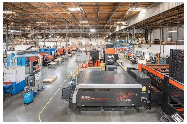
Laser cutting typically holds linear tolerances of plus or minus 0.005 to plus or minus 0.015 in and hole tolerances of plus or minus 0.005 in. CNC press brake bending holds angular tolerances within plus or minus 1 degree. These values represent realistic starting ranges for precision enclosure work, not stretch goals.
These baseline capabilities explain why formed dimensions and flange lengths vary more than flat features. Springback, tooling condition, material type, grain direction, thickness and bend count all introduce variation that same-plane features avoid, so across-bend dimensions require wider tolerances than same-plane features.
This distinction supports a strategic approach to tolerancing. Tightening only functionally critical dimensions while relaxing the rest can lower fabrication cost meaningfully on tolerance-dense sheet metal designs. Applying a blanket tight tolerance across all features increases cost without improving function.
Under these quality standards, every tolerance callout must be traceable and inspectable. Clear separation between critical mating tolerances and non-critical reference dimensions on the drawing is a prerequisite for audit-ready production.
9. Part-Count Reduction Through Clever Forming Features
Every separate part adds a tolerance stack, a fastener, an assembly step and a potential failure point. Forming features directly into the enclosure shell removes those additions and simplifies the build.
Return flanges, hems and integrated gussets add stiffness to long unsupported panels without adding parts. U-shaped channels and long unsupported flanges can twist, open, vibrate or deform under load, so designers can add return flanges, ribs, beads, gussets or hems to increase stiffness before increasing material thickness.
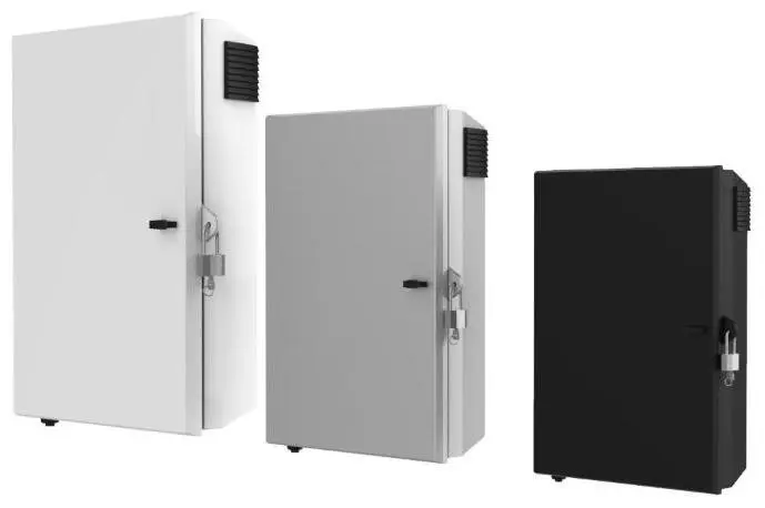
A folded sheet metal solution with appropriate bend reliefs can reduce part count to a single component and eliminate assembly labor entirely. Self-locating tabs and slots further reduce reliance on operator judgment during assembly and improve consistency across production runs.
Applying DFM Rules Before Drawing Release
The ten rules above work best when applied before drawings reach procurement, not after the first article fails inspection. Early collaboration between engineering and fabrication teams catches tolerance conflicts, tooling-access issues and hardware sequencing problems while changes remain low-cost.
Fragmented supplier networks increase lead-time variability, quality inconsistency and operational complexity. Vendor hand-offs between fabrication, finishing and assembly introduce transit time, double handling, coordination overhead and quality finger-pointing that rarely appear on individual vendor invoices. When fabrication, finishing and light electromechanical assembly flow through one partner under one purchase order, engineering changes propagate immediately instead of getting lost between vendors.
A U.S.-based integrated partner also supports reshoring goals that procurement and operations teams increasingly face from program stakeholders. The reshoring advantages discussed in material selection become more pronounced when complex fabrication and assembly stay with a single domestic source.
Fabcon engineering and quoting teams review drawings, tolerances and materials before production begins and create manufacturing routers and work instructions aligned with the floor. That front-end investment reduces rework, improves cost efficiency and ensures designs can scale from prototype through mid-volume production under certified quality systems.
Downloadable 10-Point DFM Checklist
The rules in this article are condensed into a single-page checklist that engineers can attach to drawing packages before release. The checklist covers material, bend radius, flange length, bend relief, hole placement, captive hardware, bend sequence, tolerances, part count and assembly access.
Frequently Asked Questions
Is Fabcon certified to produce enclosures for aerospace and defense programs?
Fabcon holds ISO 9001:2015 and AS9100D certifications and is ITAR registered. These certifications govern documentation, process control, traceability and quality management across fabrication, finishing and assembly. Every stage of the build is covered by integrated quality systems, so aerospace and defense procurement teams receive full traceability on every part without relying on a patchwork of vendor quality records.
Can Fabcon scale from prototype to mid-volume production without a separate onboarding process?
Fabcon agile production cells are designed to move from prototype through mid-volume production without the high minimums or rigid onboarding timelines common at large contract manufacturers. The same engineering and quality infrastructure that supports a first-article build governs production runs, so the transition becomes a ramp rather than a restart. Programs with evolving bills of materials and mixed SKUs represent a core part of Fabcon work, not an exception.
How does working with Fabcon affect total program cost compared to managing multiple vendors?
Total program cost includes more than piece price. Vendor hand-offs between fabrication, finishing and assembly introduce transit time, double handling, coordination overhead and quality finger-pointing that rarely appear on individual vendor invoices. Fabcon consolidates fabrication, finishing, powder coating, hardware insertion and light electromechanical assembly under one roof and one purchase order. That consolidation removes hidden costs that accumulate when parts move between disconnected suppliers.
What if a program already has an existing sheet metal supplier?
Most sheet metal fabricators stop at the metal and do not offer integrated powder coating, hardware insertion, wiring or electromechanical assembly. Programs that require a finished, assembled enclosure ready for deployment typically still need to coordinate two or more additional vendors after the metal is cut and formed. Fabcon handles the complete build sequence internally, which reduces vendor count, compresses timelines and eliminates the integration gaps that cause quality issues and delivery delays.
How does Fabcon maintain quality consistency across fabrication, finishing and assembly?
Fabcon certified quality management system spans the entire build, not just the fabrication step. Inspection, traceability and process controls apply equally to laser cutting, forming, hardware insertion, powder coating and final assembly. Because all operations occur in Fabcon facilities, quality data remains continuous rather than fragmented across vendor quality systems. That integrated QA structure makes audit-ready deliverables repeatable across production runs.