

Last updated: August 20, 2026
Key Takeaways for Sheet Metal DFM
- A sheet metal DFM analysis checks 3D models and flat patterns against laser-cutting, punching and press-brake limits to control cost and prevent rework.
- A structured DFM checklist covering material selection, bend radii, hole placement, flange heights, relief cuts and tolerances keeps parts moving from prototype to production without surprises.
- Seven shop-floor rules on bend radius, hole clearance, relief cuts, flange height, grain direction, radius standardization and functional tolerances remove common causes of scrap and delay.
- Applying these guidelines during quoting instead of after a purchase order prevents design-to-manufacturing disconnects that create extra setups, schedule slips and rework.
- Contact Fabcon for a DFM review and quote so the next sheet metal program moves from design to finished parts with fewer changes.
Sheet Metal DFM Checklist Fundamentals
A DFM checklist for sheet metal is a structured review that confirms a design is manufacturable before it reaches the shop floor. It covers material selection, bend radii, hole placement, flange heights, relief cuts, tolerances and finish requirements.
A thorough pre-release checklist verifies that CAD files and drawings match, bend radii and reliefs are manufacturable, holes and slots clear bend distortion zones, PEM hardware has installation clearance, cosmetic faces are defined and critical tolerances are separated from general dimensions.
Skipping this review pushes problems downstream, where they surface as rework, schedule delays and higher manufacturing costs. A DFM review before releasing a design for quoting can reduce manufacturing cost and eliminate major causes of rework and delay for laser-cut and CNC-bent parts.
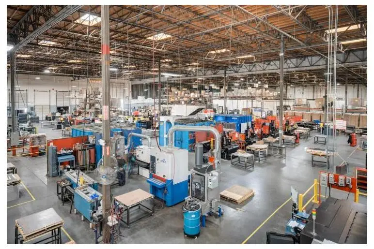
Fabcon’s engineering and quoting teams run this review together at the start of every program, so issues surface during quoting rather than during production.
Get a quote from Fabcon’s engineering team.
Core Sheet Metal DFM Guidelines
Sheet metal DFM guidelines translate press-brake and laser-cutting process limits into design rules. The core categories are bend radius, hole and slot placement, flange height, bend relief, tolerance assignment, material selection and finish specification.
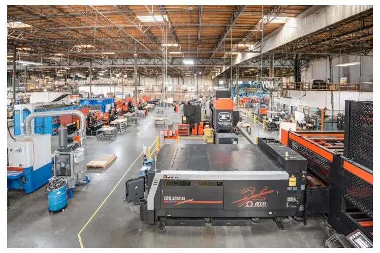
Each category has quantifiable thresholds. Achievable tolerances vary significantly by feature. Applying blanket tight tolerances across all features forces extra setups and raises cost without improving function.
Tolerance stack-up from five consecutive folds, each at standard commercial tolerance, can cause the final flange to drift from nominal and misalign mounting holes in multi-panel assemblies. Identifying the one or two critical mating dimensions and applying general tolerances everywhere else keeps cost in check.
The seven rules below turn these categories into specific shop-floor practices that prevent the most common causes of rework and scrap.
7 Shop-Floor DFM Rules That Prevent Rework
Rule 1: Match Bend Radius to Material and Temper
Set the inside bend radius at or above the material-specific minimum. Temper is as important as alloy. Annealed 5052-O aluminum allows a 0T radius, while harder tempers require larger radii, as detailed in the bend radius table below.
Failure example: A 2 mm 6061-T6 part specified with an R2 inside radius produced cracked parts. Switching to 5052-H32 with the same radius produced zero cracks.
Fix: Use the bend radius table in the next section to select a safe minimum. When uncertainty exists, increase the chosen minimum radius to provide margin against lot-to-lot ductility differences.
Rule 2: Keep Holes and Slots Clear of Bend Lines
Holes placed too close to a bend line distort during forming. Holes must be kept a minimum distance from bend lines to prevent distortion, and slots follow different spacing rules. The hole-to-bend distance table below lists specific values by feature type.
Failure example: Holes that oval on the bend radius are among the most common forming problems caught in DFM review. Ovalized holes cause assembly failures at the customer’s line.
Fix: Reference the hole-to-bend distance table below. For PEM hardware, allow additional clearance for the insertion press beyond the standard hole-to-bend distance.
Rule 3: Add Bend Relief at Every Flange Intersection
Where two flanges meet at a corner, omitting a relief cut concentrates stress and tears the material during forming. For most materials, bend relief notches should have a width of at least 50% of material thickness and extend past the bend tangent.
Failure example: Box designs lacking corner relief are a recurring DFM flag. The tear propagates into the part face, which requires scrap or weld repair.
Fix: Relief cuts should have a width of at least 50% of material thickness, extend past the bend tangent line and include a minimum radius at the relief corner to reduce stress concentration. A round hole centered on the intersection often works better than a narrow slot for laser-cut parts.
Rule 4: Respect Minimum Flange Height
Short flanges fall into the die cavity, which produces inconsistent bend angles and damaged surfaces. The practical minimum flange height for press-brake air bending is 4 times material thickness plus the inside bend radius.
Failure example: High-volume runs with undersized flanges can produce scrap due to cumulative springback and tool wear, plus ovalized holes that cause assembly failures.
Fix: Maintaining this minimum prevents flanges from slipping, rolling or forming out of square. Keep flange heights consistent across a part to reduce tooling changes.
Rule 5: Orient Critical Bends Perpendicular to Grain Direction
Rolling grain direction controls crack risk during bending. Bending perpendicular to the rolling grain allows tighter radii, while bending parallel to the grain increases crack risk, especially in aluminum.
Failure example: Bending parallel to the grain requires adding 50% to the minimum bend radius compared with perpendicular-to-grain bends. Ignoring this on 6061-T6 or high-strength steel produces cracked outer fibers.
Fix: Orient the flat pattern so critical bends run across the grain. When layout constraints force a parallel-to-grain bend, increase the radius accordingly and flag it in the DFM review.
Rule 6: Standardize Bend Radii and Minimize Bend Count
Every unique bend radius requires a tooling change and extra programming. Bend radii should be standardized to a single value per part to reduce tooling changes and programming time.
Cost impact: Parts with four or fewer bends are typically faster to form than those with eight or more bends, because each bend adds setup time, a hit and variation risk.
Fix: Audit the part for bends that serve no structural or assembly function. Replace complex formed features with welded tabs or PEM hardware where that approach maintains performance. Standardize to 90-degree bends wherever geometry allows.
Rule 7: Assign Tolerances Only Where Function Requires
Blanket tight tolerances force manual adjustments, slower feed rates and continuous inspection. Applying tight tolerances to every dimension forces extra setups and higher costs without improving function.
Failure example: Specifying tolerances tighter than standard commercial limits forces secondary manual adjustments, slower machine feed rates and continuous CMM inspections, which increases labor costs.
Fix: Identify the one or two critical mating dimensions and apply tight tolerances only there. Use ISO 2768-m general tolerances for all other features to avoid unnecessary precision. Calculate tolerance stack-up on multi-bend parts before release to confirm that accumulated variation still keeps critical dimensions within specification.
Get a quote and have Fabcon’s engineers review the design before production begins.
Bend Radius Guidelines by Material
The table below lists minimum inside bend radii as a multiple of material thickness (T) for common alloys, bending perpendicular to grain with standard press-brake tooling. Use these values as an absolute floor and increase for production designs to account for sheet thickness variation and lot-to-lot ductility differences.
| Material | Condition / Grade | Min. Inside Bend Radius (perpendicular to grain) | Notes |
|---|---|---|---|
| Aluminum 5052 | H32 | typically 1T to 1.5T depending on thickness | Preferred alloy for tight radii, hems and offsets |
| Aluminum 6061 | T6 | 1-1/2T | Lacks ductility for bending; consider 5052 as substitute |
| Cold-rolled steel (CRS) | 1008-1018 | Varies by thickness and condition | Safe default for most mild steel applications |
| Hot-rolled steel (HRS) | A36 / A1011 | Varies by thickness and condition | Grain direction adds 50-100% to radius when bending parallel |
| Stainless steel 304 / 316 | Annealed (2B) | 0.5T-1T; 1T recommended as practical default | Greater springback than mild steel; overbend to hit target angle |
| Stainless steel 430 | Ferritic | Varies by thickness and condition | 1.5T-2.0T for 316/430 in heavier gauges |
| Grade 2 Titanium | Commercially pure | Varies by thickness and condition | High-strength materials require greater forming forces and tighter process control |
Bend radius choices interact with hole spacing and flange height, so the next section focuses on hole-to-bend distance rules that protect features during forming.
Hole-to-Bend Distance Rules
The table below consolidates minimum spacing requirements for holes, slots and edges relative to bend lines. Hole-to-edge and hole-to-bend distances are common trouble spots, because features placed too close to a bend line stretch or distort during forming.
| Feature Type | Minimum Distance from Bend Line | Measurement Basis | Source |
|---|---|---|---|
| Round hole (laser or punched) | 2t + r (≤25 mm diameter) or 2.5t + r (>25 mm) | Edge of hole to bend tangent line | V&DF design guide |
| Slot | 2.5T + bend radius | Edge of slot to bend tangent line | PTC design rules |
| PEM / self-clinching hardware hole | Sufficient distance to accommodate insertion press | Edge of hole to bend tangent line | R&I Industries press-brake DFM guide |
| Hole center to sheared edge | 1T to 2T | Hole center to part edge | Simulations4All DFM checker |
For 1.5 mm material with a 1.5 mm inside bend radius, the minimum hole-center-to-bend-tangent distance depends on the specific hole diameter and bend radius. Confirm these values with the fabricator before releasing DXF files, because a 0.5 mm error per bend accumulates and prevents parts from assembling correctly.
Download the DFM Analysis Template
Fabcon’s DFM analysis template mirrors the seven rules above in a structured checklist format. It covers material and temper selection, bend radius verification, hole-to-bend spacing, relief cut geometry, flange height, tolerance assignment and finish specification. Engineering teams use it during internal design review before submitting an RFQ.
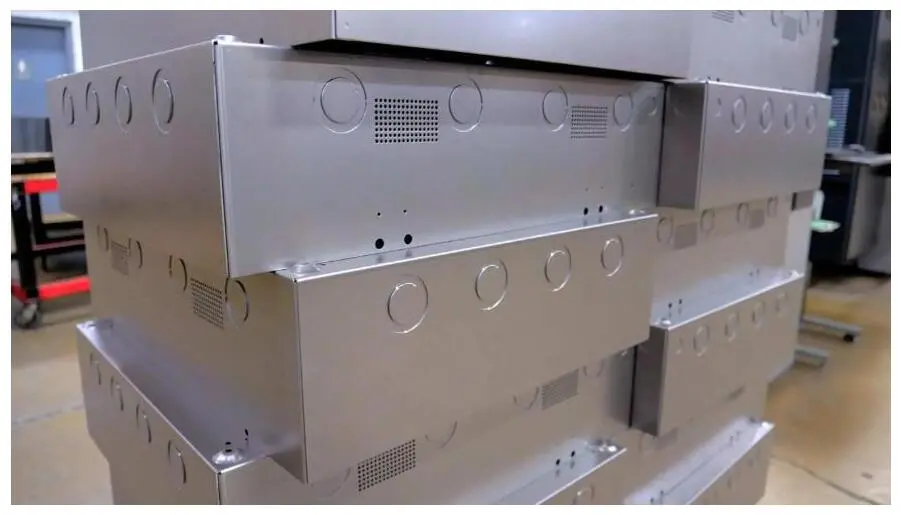
A complete RFQ package should include a solid 3D CAD model, flat pattern, dimensioned 2D drawing, material grade, quantities, bend-radius assumptions, hardware lists, weld symbols, surface-finish requirements, cosmetic surface classifications and inspection requirements. Submitting a complete package at quoting eliminates scope changes and rework downstream.
Get a quote and request the DFM checklist from Fabcon’s engineering team.
Frequently Asked Questions
What is the difference between a DFM analysis and a standard design review?
A standard design review checks whether a part meets functional and performance requirements. A DFM analysis checks whether the part can be manufactured reliably and economically with the specific processes the fabricator uses. DFM covers press-brake tooling limits, laser-cutting kerf, bend radius minimums, hole placement, flange heights, relief cuts and finish compatibility. A design can pass a functional review and still trigger rework, extra setups or scrap once it reaches the shop floor. Running both reviews before releasing for production is the most effective way to prevent schedule slips.
Why does material temper matter as much as alloy selection for sheet metal bending?
Temper determines ductility, and ductility sets the minimum bend radius a material can tolerate without cracking. Two parts of the same alloy in different tempers can require significantly different bend radii. Specifying 6061-T6 where 5052-H32 would serve the same function is one of the most common and costly DFM errors in sheet metal design. The T6 temper lacks the ductility for tight radii, hems and offsets. Reviewing temper alongside alloy during DFM analysis prevents cracked parts and material substitution delays.
How does Fabcon apply DFM rules during quoting rather than after a purchase order is placed?
Fabcon’s engineering and quoting teams review drawings, tolerances and materials together before a quote is issued. They check bend radii against material and temper, verify hole-to-bend distances, confirm flange heights, flag missing relief cuts and identify tolerance assignments that exceed process capability. Issues are resolved through direct collaboration with the customer’s engineering team at the quoting stage, when changes are simple and inexpensive. This approach eliminates the design-to-manufacturing disconnect that causes rework, extra POs and schedule slips when problems surface during production.
What happens to hole tolerances and fit after powder coating?
Powder coating adds measurable thickness per side. On mating interfaces, this buildup can close slots, fill grounding points and cause binding in slip joints and hinges. Hole sizes, fits and mating surfaces must account for coating buildup before the design is released. Cosmetic and functional surfaces requiring masking or conductivity must be identified during DFM review and called out explicitly on the drawing. Fabcon’s in-house finishing capability means coating thickness, masking requirements and assembly fit are coordinated under one roof rather than managed across separate vendors.
Can Fabcon support both prototype and production volumes under the same DFM framework?
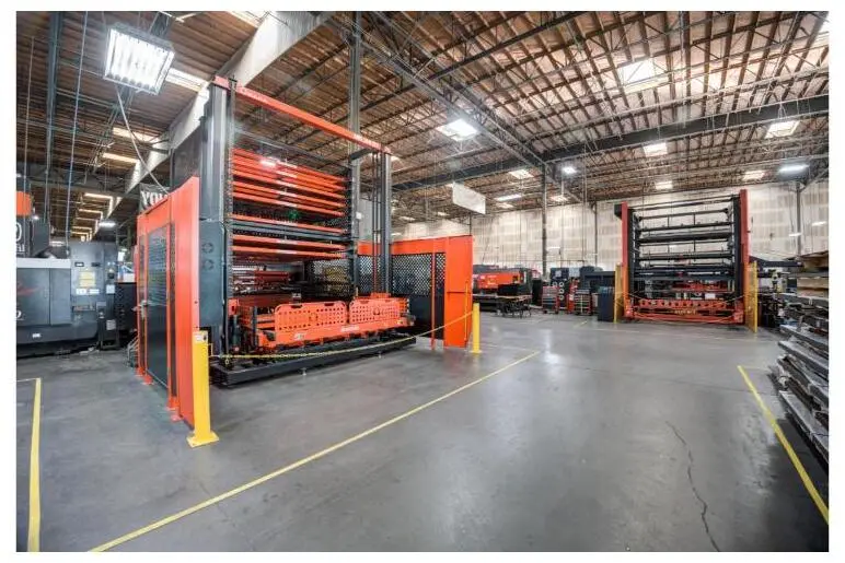
Fabcon’s agile production cells support programs from prototype through mid-volume production without requiring separate onboarding or tooling strategies for each phase. The DFM rules applied during quoting are the same rules that govern production, so the transition from prototype to production does not introduce new manufacturability constraints. Fabcon’s vertically integrated facility covers fabrication, finishing and light electromechanical assembly under one roof, which means the same engineering team that reviewed the prototype design supports the production build without vendor handoffs or coordination gaps.