
Last updated: August 23, 2026
Key Takeaways for Server Rack Bonding Compliance
- Server rack enclosure bonding must satisfy both TIA-607 equipotential requirements and NEC Article 250 fault-current safety standards to protect equipment and pass inspection.
- ANSI/TIA-607-C mandates a minimum 6 AWG copper conductor for each rack bonding jumper, with dedicated runs required instead of daisy-chained connections.
- Powder coating acts as an electrical insulator, so masking bonding surfaces before coating or mechanically removing paint afterward is essential for reliable continuity.
- Enclosure design features such as pre-masked bonding pads, grounding bosses and integrated RBB mounting points simplify field installation and reduce inspection failures.
- Partner with Fabcon early in the design process to engineer TIA-607 and NEC-compliant bonding features directly into server rack enclosures.
Equipotential Bonding Fundamentals for Server Rack Enclosures
Equipotential bonding connects all metallic components in a telecommunications space to a common reference so that no voltage difference exists between them. The goal is a zero-voltage-difference plane across rack frames, cable trays and equipment chassis.
A properly bonded rack delivers three functions. It provides a low-impedance fault-current path that trips overcurrent devices. It establishes an equipotential reference across the row that prevents voltage differences a technician could bridge. It also provides an ESD reference path required by IT equipment.
Without effective bonding, voltage potentials develop between equipment, leading to data corruption, equipment damage and personnel safety risks. Robust, low-impedance grounding and bonding are equally important as UPS filtering for EMI mitigation, providing a safe path for induced currents to dissipate. Achieving that low-impedance path depends on proper conductor sizing and connection methods.
TIA-607 Conductor Requirements for Server Racks
ANSI/TIA-607-C requires that metallic components in computer rooms bond to the Primary Bonding Busbar or Secondary Bonding Busbar using a minimum 6 AWG conductor.
The Rack Bonding Jumper that connects the rack frame and its Rack Bonding Busbar to the serving SBB must be a 6 AWG copper conductor unless the equipment manufacturer specifies a larger size. Larger conductors suit long rack rows or high-density cabinets because they reduce DC resistance and surge impedance.
Common practice for connections to the RBB includes exothermic welding or two-hole lugs. Two-hole compression lugs sized for the conductor and the busbar hole pattern typically terminate conductors on the PBB, SBB and RBB.
How NEC Article 250 Differs from TIA-607
NEC Article 250 establishes grounding and bonding requirements for electrical safety. It requires an equipment grounding conductor sized per Table 250.122 to provide a low-impedance fault-current path that ensures overcurrent devices trip during ground faults. Its focus is shock protection and fault-current return for power systems.
TIA-607 addresses a different problem. The TIA-607 telecommunications bonding architecture forms a common bonding network (CBN) or mesh bonding network (mesh-BN). It interconnects all metallic telecommunications components to reduce EMI, ESD and interference, distinct from the NEC Article 250 focus on the service grounding electrode system and fault-current return paths.
ANSI/TIA-607-E uses a single-point tree-topology connection to the building grounding electrode system exclusively at the PBB. It prohibits multiple paths that would create ground loops, in contrast to standard NEC Article 250 practices that may permit multiple grounding paths.
Both standards must be satisfied. TIA-607-B explicitly references the NEC and National Electrical Safety Code (NESC) as normative documents, so telecommunications bonding installations must also satisfy applicable local and national electrical code requirements for safety. Designers must engineer enclosures to meet Article 250 fault-current requirements and TIA-607 equipotential and high-frequency performance at the same time.
Paint Removal and Surface Prep for Bonding Continuity
Powder coating functions as an electrical insulator. Standard powder coatings have electrical resistivity of 1012 to 1016 ohm-centimeters, so they interrupt bonding continuity at any coated interface.
Painted contact surfaces represent the single most common cause of enclosure grounding and bonding inspection failures because they break the low-impedance metallic path required by NEC Article 250 and UL 508A.
Fabricators can prevent this failure through three approaches, each suited to different production constraints and reliability requirements.
- Masking before coating: Silicone plugs, caps, high-temperature tape, threaded caps and custom masking fixtures improve repeatability when protecting grounding points during powder coating. This method protects bonding pads from coating so they remain bare metal.
- Post-coat removal: Grinding, scraping or chemical stripping exposes bare metal at bonding pads after finishing. Fabrication specifications must require mechanical removal down to bare metal, followed by application of a corrosion-inhibiting compound before making the connection.
- Self-piercing hardware: Self-piercing grounding screws and star washers that cut through the coating to reach the substrate are commonly used solutions for maintaining grounding continuity on powder-coated server racks. Star washers are not a substitute for a properly masked or bare-metal contact surface when the powder coat finish is thicker.
Removal of paint from bonding contact areas is recommended. Masking at the fabrication stage is the most reliable method because it eliminates field variation and produces a consistent, inspectable bonding surface on every unit.
Dedicated Bonding Conductors Versus Daisy Chains
TIA-607-C section 7.1.4 prohibits serial bonding. Cabinets, racks and other enclosures cannot be bonded in series, and each enclosure requires its own dedicated bonding conductor back to the mesh-bonding network, PBB, SBB or TEBC.
A break in a daisy chain can leave downstream racks unbonded, which creates a compliance failure that is difficult to detect without systematic testing. A common shortfall in data center projects is racks bonded through cable tray rather than directly to the bonding network.
Commercial data center installations require individual 6 AWG runs from each rack RBB or bonding point to the SBB or PBB. Home-lab or low-density environments may use simplified approaches, but any installation subject to TIA-607 inspection must follow the dedicated-conductor requirement. The standard does not provide exceptions based on rack count or density.
Step-by-Step Busbar and Jumper Installation
The following sequence applies to rack bonding busbar installation per TIA-607-C requirements.
- Verify that the rack bonding point is bare metal or has been masked before coating. Remove any coating at the mounting location and apply a corrosion-inhibiting compound.
- Mount the RBB on the rack using insulators that provide separation from the rack frame.
- Bond the RBB to the rack frame using a listed Rack Bonding Jumper or listed paint-piercing bonding washers that make contact with the underlying conductive metal.
- Connect all detachable metallic parts to ground by grounding or bonding jumpers, or through the cabinet frame to the cabinet bonding conductor connection point.
- Terminate all conductors on the RBB using two-hole compression lugs on appropriate spacing, installed with manufacturer-specified torque and crimp tools.
- Run a dedicated 6 AWG copper conductor from the RBB to the SBB or PBB. Do not share this run with adjacent racks.
- Make connections to the TEBC with listed irreversible compression connectors.
- Test continuity at each bonding point and document results for inspection.
Request a quote for enclosures with pre-masked bonding points and integrated RBB studs.
Enclosure Design Features That Support Field Bonding
Bonding compliance becomes easier when enclosure features support it from the start. Enclosure designers should plan bonding paths early so that masking specifications can be integrated into the fabrication router before parts enter the coating line, which eliminates the need for post-finish paint removal.
Design features that support reliable field bonding include:
- Grounding bosses and PEM studs: Dedicated bonding hardware such as grounding bosses, threaded studs and PEM fasteners creates a stable electrical path instead of relying on incidental metal contact.
- No-paint zones: Specifying conductive zones on engineering drawings ensures that the masking approach discussed earlier is applied consistently across production runs.
- Integrated RBB mounting features: Pre-drilled insulator mounting holes and captive hardware eliminate field drilling and reduce the risk of incorrect busbar placement.
- Flexible bonding straps for doors and panels: Flexible grounding straps or copper braids provide reliable bonding continuity for lids, doors or parts subject to movement and vibration where rigid metal joints could lose contact over time.
- Conductive gaskets at seams: Conductive gaskets and EMI shielding materials create electrical contact along enclosure seams and openings, which improves shielding performance when continuity depends on more than isolated screw points.
Fabcon DFM collaboration addresses these requirements at the design stage. Engineering and quoting teams review drawings before production begins, identify bonding paths, specify masking zones and integrate busbar mounting features into the fabrication router.
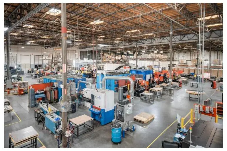
Because fabrication, finishing and assembly operate under one roof, selective masking aligns with the powder coat process instead of passing to a separate vendor. This structure removes the vendor handoff that often causes bonding non-compliance in fragmented supply chains and keeps a single accountable partner in control from raw sheet metal through finished, ready-to-bond assembly.
Request a quote and discuss DFM requirements with the Fabcon engineering team.
Frequently Asked Questions
What is the difference between TIA-607 and NEC Article 250 for server rack bonding?
NEC Article 250 governs electrical safety grounding for power systems, focusing on fault-current return paths that trip overcurrent devices and protect personnel from shock. TIA-607 governs telecommunications bonding, targeting equipotential performance and high-frequency EMI and ESD control across rack frames, cable trays and equipment chassis. Both standards apply to data center installations, as discussed in the NEC versus telecom bonding section. Designing to only one standard creates compliance gaps that inspectors and commissioning teams will identify.
Why does powder coating cause bonding inspection failures?
Standard powder coating is an electrical insulator. When a bonding lug or conductor terminates on a coated surface, the coating interrupts the metal-to-metal contact required for a low-impedance bonding path. The connection may appear mechanically secure but will fail continuity testing.
Reliable bonding requires either masking the bonding pad before coating so it remains bare metal, mechanically removing the coating after finishing or using self-piercing hardware such as star washers. Masking at the fabrication stage is the most consistent method because it is controlled before the part enters the coating line rather than corrected in the field.
Can racks be bonded in series to reduce conductor runs?
No. TIA-607-C section 7.1.4 explicitly prohibits serial or daisy-chain bonding of cabinets and racks. Each enclosure must have its own dedicated bonding conductor running back to the mesh-bonding network, PBB, SBB or TEBC. As noted in the dedicated conductor section, any break in the chain leaves downstream racks unbonded. Individual conductor runs are required regardless of rack count or row density.
What enclosure features should procurement teams specify to reduce field rework?
Procurement teams should specify enclosures with pre-masked or bare-metal bonding pads at all conductor termination points and integrated RBB mounting features such as insulator standoffs and pre-drilled holes. Grounding bosses or PEM studs at door and panel bonding locations and engineering drawings that identify no-paint zones also support consistent results.
These features shift bonding compliance from a field installation problem to a fabrication-controlled outcome. Sourcing from a manufacturer that controls fabrication, finishing and assembly under one roof reduces the risk that masking specifications are lost between vendors.
How does DFM collaboration affect bonding compliance for high-mix programs?
High-mix programs involve multiple enclosure configurations with varying rack heights, busbar positions and panel layouts. Without early DFM collaboration, bonding features often become inconsistent across SKUs, which creates inspection failures on some configurations but not others.
DFM review before production begins allows the engineering team to standardize bonding pad locations, masking zones and hardware insertion across the bill of materials. This approach produces consistent, inspectable bonding on every configuration instead of relying on field technicians to adapt to enclosure-by-enclosure variation.
Conclusion: Build Bonding Compliance into Fabrication
Post-fabrication fixes for bonding non-compliance such as field paint removal, added hardware and conductor rerouting consume time and introduce variation that is difficult to document for inspection. The risks compound in high-density deployments where dozens of racks must each meet TIA-607 and NEC requirements.
Bonding compliance starts as a fabrication-stage decision. Enclosures with pre-masked bonding pads, integrated RBB mounting features and DFM-reviewed conductor paths arrive at the installation site ready to bond. They reduce field labor, eliminate rework and produce consistent inspection results across every unit in a program.
Fabcon vertically integrated facilities combine precision sheet metal fabrication, in-house finishing with selective masking and light electromechanical assembly under one roof. Engineering teams collaborate on DFM before production begins, so bonding features are built into the enclosure instead of corrected after the fact.
Get a quote for custom server rack enclosures engineered for TIA-607 and NEC compliance.