
Key Takeaways for Enclosure DFM
- Sheet metal enclosure DFM reduces rework by reviewing geometry, materials, hardware and tolerances before production begins.
- Common failure modes include incorrect bend radii, missing bend relief and hardware placed on the wrong insertion side.
- Material selection must match environmental demands, such as aluminum for weight and thermal performance, stainless for corrosion resistance and carbon steel for structural applications.
- Interlocking tabs, clear datums and default tolerances reduce welding, limit stack-up error and lower assembly labor.
- Fabcon provides integrated DFM reviews that keep enclosure programs on schedule and within budget from prototype through production.
Bend Geometry: First Checkpoint for Reliable Enclosures
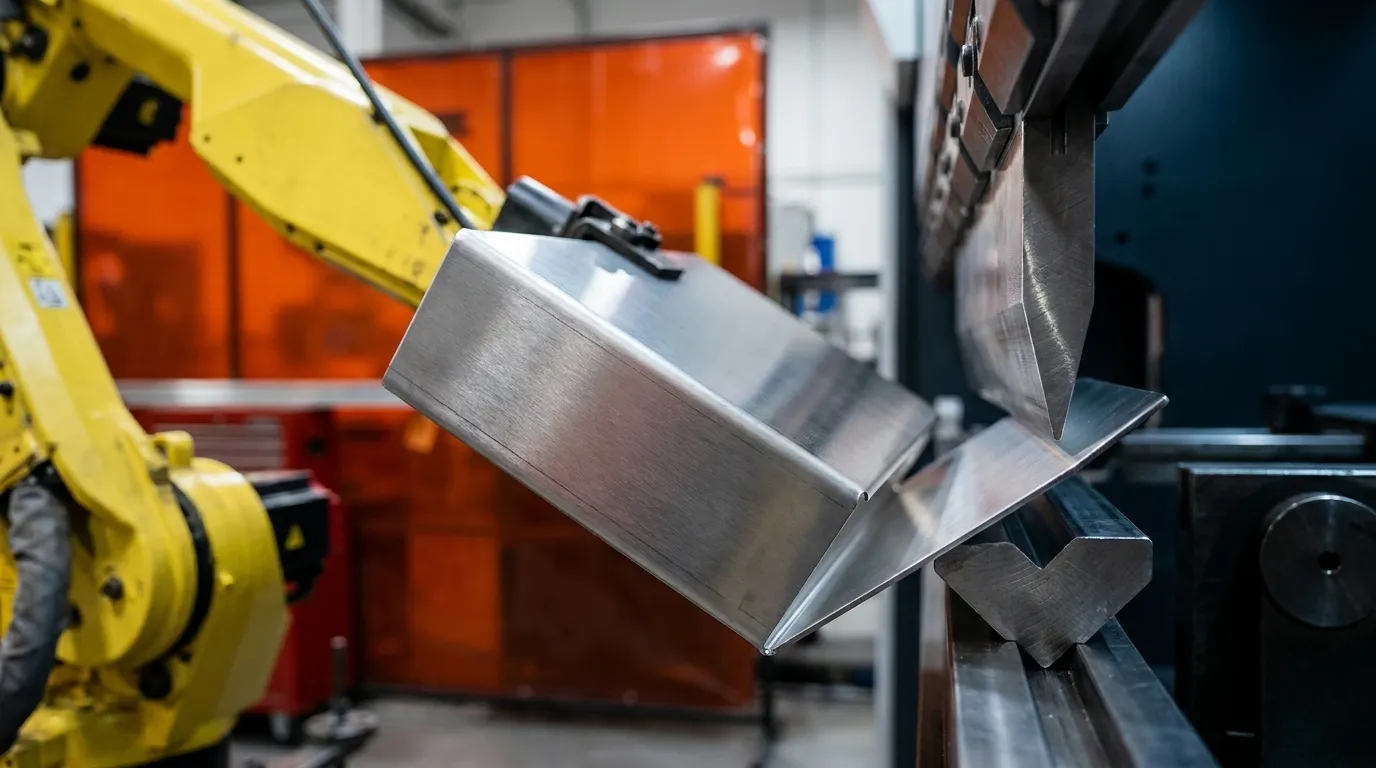
Bend geometry drives most first-article failures in sheet metal enclosures. Standard practice sets the inside bend radius equal to material thickness, with aluminum tolerating tighter radii than stainless steel or carbon steel. A radius below the material minimum causes cracking at the bend line. Missing bend relief at notches and corners causes tearing during forming.
Bend relief must be incorporated to avoid material tearing and to ease the forming process. Holes and slots placed too close to a bend distort during forming and shift critical dimensions. Air bending on a CNC press brake produces typical tolerances of ±0.010 in. on bend-line position. K-factor errors on multi-bend parts can shift critical dimensions by a meaningful margin when the fabricator process data does not calibrate flat patterns.
Before: An enclosure panel for an energy storage cabinet specified an inside radius below the minimum for the selected alloy. First-article parts cracked at two corners, which required a material substitution, new flat patterns and a full re-run.
After: A DFM review before tooling confirmed the correct minimum radius for the alloy and added bend relief at all notched corners. First-article parts passed dimensional inspection without rework.
Hardware and Fastener Details that Protect Assembly Labor
Once bend geometry is validated, the next major failure point appears at assembly. Hardware placement errors are the second leading cause of assembly labor overruns in enclosure programs. Hardware drawings must specify the PEM or self-clinching fastener part number, insertion side and installed orientation to support correct assembly of panels and brackets. Designers should include hardware in the CAD model and add gaps of 0.005–0.015 in. for all connecting parts to support assembly without interference.
Incorporating PEM inserts in sheet metal enclosures improves assembly efficiency and reduces the risk of misalignment. Self-locating tabs and slots simplify assembly and reduce fastener count, which directly reduces labor time at the assembly station.
Before: A data center rack enclosure reached the assembly stage with press-in nuts specified on the wrong panel face. Technicians discovered the interference condition during first build, which required manual rework on every unit in the pilot run.
After: A DFM review flagged the insertion-side conflict in the CAD model. The drawing was corrected before tooling, and the pilot run assembled without intervention.
Material Selection by Environment and Application
Material selection determines whether an enclosure meets durability, corrosion, weight and compliance requirements across its service life. Stainless steel is reserved for harsh environments because of its cost premium relative to carbon steel, while aluminum offers low weight, heat dissipation and corrosion resistance but is not suitable for high-impact applications. Material callouts on drawings must specify alloy, temper and thickness because each parameter affects formability, strength and tooling selection.
Vertical-specific material decisions follow consistent patterns. Data center enclosures prioritize aluminum for thermal management and weight in rack-mounted configurations. Energy storage and power distribution enclosures require weatherproof alloys and coatings compatible with outdoor thermal cycling. Traffic safety and transportation structures use infrastructure-grade carbon steel with corrosion-resistant finishing.
Medical device assemblies require materials with full traceability and finishes compatible with cleaning protocols. Aerospace and defense programs specify alloys and processes that meet AS9100D and ITAR requirements, with full dimensional traceability.
In high-temperature environments, designers should use materials with compatible thermal expansion coefficients, incorporate flexible joints where dimensional change is expected and set tolerances that accommodate slight shifts. A wrong alloy choice at the design stage forces a material change after tooling, which resets flat patterns, bend radii and finishing specifications.
Assembly Strategy and Tolerance Control
Flat-pattern layout and tolerance stack-up decisions made at the design stage determine whether welding and final integration proceed without fixtures or rework. Interlocking tabs can replace or reduce welding by holding parts in place, increasing strength and eliminating issues such as material shrinkage, complex fixtures, corner gaps and cracking.
Dimensions spanning multiple bends are not recommended as a primary dimensioning scheme because they increase stack-up and forming error. Default sheet metal tolerances within a 12-inch envelope include ±0.005 in. for sheared edge to hole, ±0.010 in. for formed edge to hole, ±0.015 in. across two bends and ±0.030 in. for holes across two or four bends. Tolerances tighter than the process supports increase cost without improving fit.
Before: A medical equipment cart assembly specified overall formed-part dimensions as primary datums across four bends. Cumulative stack-up caused consistent misalignment at the weld joints, which required hand-fitting on every unit.
After: A DFM review re-established datums at sheared edges and added interlocking tabs at the weld joints. Assembly time dropped and weld quality became consistent across the production run.
7-Step Sheet Metal Enclosure DFM Review Checklist
The following checklist consolidates the four failure-mode categories into seven checkpoints. Each step targets a specific design decision that can cause rework or assembly delays. Teams can apply this sequence at the design stage before submitting for quote or tooling.
Step 1: Bend geometry. Common failure mode involves the bend radius and relief issues discussed above. Recommended action is to confirm that the inside radius meets material minimums and that bend relief appears at all notched corners. This step prevents cracking and tearing on first article.
Step 2: Hole and slot placement. Once bend geometry is validated, the next risk involves features too close to bends or edges, which causes distortion during forming. Recommended action is to position holes at least one material thickness from edges and farther from bends so features remain stable through the bending process confirmed in Step 1.
Step 3: Hardware and fasteners. After feature placement is stable, hardware details become critical. Common failure modes include wrong insertion side, missing clearance gaps and misalignment at assembly. Recommended action is to specify PEM part number, insertion side and orientation, and add 0.005 to 0.015 in. clearance gaps in CAD to protect assembly throughput.
Step 4: Material callout. With geometry and hardware defined, material clarity prevents late-stage changes. Common failure modes include unspecified alloy, temper or thickness and a material that does not match the environment. Recommended action is to specify alloy, temper and thickness and align material with corrosion, weight and compliance requirements for the target application.
Step 5: Tolerance stack-up. Once material is set, tolerance strategy controls fit and labor. Common failure modes include multi-bend datums and tolerances tighter than process capability. Recommended action is to datum from sheared edges and use default tolerances unless fit-critical features require tighter specifications that the process can support.
Step 6: Flat-pattern and tab design. After tolerances are stable, the flat pattern and joining strategy define welding effort. Common failure modes include welding where tabs could replace it, shrinkage and fixture complexity. Recommended action is to use interlocking tabs to replace welds where practical and add rounded corners on tabs to reduce stress concentration and ease insertion.
Step 7: Finishing and assembly sequence. The final checkpoint aligns coating, hardware and inspection. Common failure modes include undefined coating or hardware insertion sequence and missing inspection datum. Recommended action is to define inspection condition, such as post-coat, post-hardware or post-weld, and identify datum surfaces in an assembly sketch so quality checks match the real build.
Conclusion: Turning DFM into a Repeatable Enclosure Process
The four pillars of sheet metal enclosure DFM, bend geometry, hardware and fasteners, material selection and assembly and tolerance control, address the failure modes that drive rework, vendor handoffs and total program cost. Applying the 7-step checklist at the design stage, before tooling or first article, provides the most cost-effective point to resolve these issues.
The North American contract fabrication services market reached USD 65.95 billion in 2025, and reshoring and foreign direct investment announcements totaled 244,000 U.S. manufacturing jobs in 2024, which reflects a structural shift toward domestic, integrated suppliers. Engineering and procurement teams that consolidate supply chains benefit from one accountable partner that combines precision fabrication, finishing and light electromechanical assembly under one roof to eliminate fragmented handoffs and maintain short lead times from prototype through mid-volume production.
Fabcon operates as a vertically integrated U.S. precision fabrication and assembly partner, founded in 1977, with ISO 9001:2015 and AS9100D certified quality systems governing every stage of the build. The engineering and quoting teams review drawings, tolerances and materials before production begins so that designs can be built at scale with materials and processes that meet durability expectations across data center, energy storage, traffic safety, medical device and aerospace programs.
Submit an enclosure program to Fabcon for a full DFM review and detailed quote.
Frequently Asked Questions
What is the difference between a DFM review and a standard fabrication quote?
A standard fabrication quote prices a design as submitted. A DFM review evaluates the design before quoting to identify bend geometry violations, hardware placement conflicts, material mismatches and tolerance stack-up issues that cause rework or quality failures in production. The DFM review produces a revised drawing package and manufacturing router aligned with the fabrication floor, so the quote reflects a design that can be built consistently at scale. Skipping the DFM step often results in change orders, first-article failures and higher total program cost.
When in the product development cycle should a DFM review occur?
The most cost-effective point for a DFM review occurs at the detailed design stage, after enclosure geometry is defined but before tooling is released or a pilot run is ordered. Changes made at the design stage cost a fraction of changes made after first article. For programs moving from prototype to mid-volume production, a DFM review at the transition point catches design decisions that worked at low quantities but create quality or throughput problems at higher volumes, such as weld joints that could be replaced by interlocking tabs or tolerance callouts that exceed process capability.
How does vertical integration affect DFM outcomes for sheet metal enclosures?
When fabrication, finishing and light electromechanical assembly operate under one roof, the DFM review can address the full build sequence rather than only the metal forming steps. Finishing processes such as powder coat or CARC military-grade coating affect final dimensions and hardware clearances. Assembly sequences determine whether interlocking tabs or weld joints are more practical. A vertically integrated partner can align all of these decisions, while a build-to-print job shop reviews only the sheet metal geometry and leaves finishing and assembly conflicts to be discovered downstream. Vertical integration also removes vendor handoff delays and quality disputes that occur when fabrication, coating and assembly are managed across separate suppliers.
What industries benefit most from sheet metal enclosure DFM services?
Any industry that requires precision enclosures at mid-volume production benefits from DFM services, and the impact is strongest in sectors with strict environmental, compliance or integration requirements. Data center programs require rack-mounted enclosures with tight dimensional tolerances for cooling and cable management. Energy storage and power distribution programs require weatherproof enclosures with electromechanical integration. Traffic safety and transportation programs require infrastructure-grade structures built to compliance standards. Medical device programs require full material traceability and finishes compatible with cleaning protocols. Aerospace and defense programs require AS9100D and ITAR-compliant manufacturing with dimensional traceability across every stage of the build.
How does early DFM collaboration reduce total cost of ownership for enclosure programs?
Total cost of ownership for an enclosure program includes fabrication cost, rework, scrap, assembly labor, vendor coordination time and schedule delays. DFM collaboration reduces all of these by resolving design issues before they reach the production floor. Correcting a bend radius specification in a drawing consumes engineering time. Correcting the same issue after first-article inspection adds tooling changes, material scrap, re-inspection and schedule impact. For programs with multiple enclosure variants or evolving bills of materials, a DFM framework applied consistently at each design revision prevents cumulative cost growth and keeps the program on schedule from prototype through mid-volume production.