
Key Takeaways
- DFM review for custom metal enclosures removes features that cause distortion, tolerance stack-up, hardware conflicts and finish failures before production.
- Following the 10-rule checklist, including bend reliefs, minimum hole-to-bend distances and proper hardware placement, prevents common forming defects and reduces scrap.
- Accounting for finish thickness, material properties and post-bend tolerances during design keeps mating surfaces, threads and assembly fit within specification after coating.
- Validating DFM against production tooling and processes, rather than prototype methods, prevents systematic defects when scaling from low to mid-volume runs.
- Early collaboration with Fabcon’s engineering team supports reliable scaling and consistent quality compliance.
The 10-Rule DFM Checklist for Custom Metal Enclosures
- Add bend reliefs at every interior corner. Relieve stress at bend terminations to prevent tearing and distortion.
- Maintain minimum hole-to-bend distance. Keep holes and slots clear of bend zones to prevent deformation.
- Specify minimum bend radius per material and gauge. Tighter radii than the material allows cause cracking and springback.
- Account for bend deduction in flat-pattern layout. Incorrect bend allowance creates cumulative dimensional error.
- Locate hardware insertion points away from bend zones. Self-clinching fasteners require sufficient material support to seat correctly.
- Design clearance for powder coat or wet paint buildup. Finish thickness affects mating surfaces, thread engagement and panel fit.
- Consolidate tolerance stack-up across the assembly axis. Each bend adds dimensional variation. Critical datums should reference a single face.
- Avoid features that require secondary operations on bent parts. Machining or punching after forming increases cost and introduces positional error.
- Standardize hardware across the BOM. Mixed fastener families increase tooling setups and assembly error risk.
- Validate DFM against the production process, not just the prototype process. Fixturing, tooling and press brake programs differ between low-volume and mid-volume runs.
Bend Reliefs for Reliable Corners
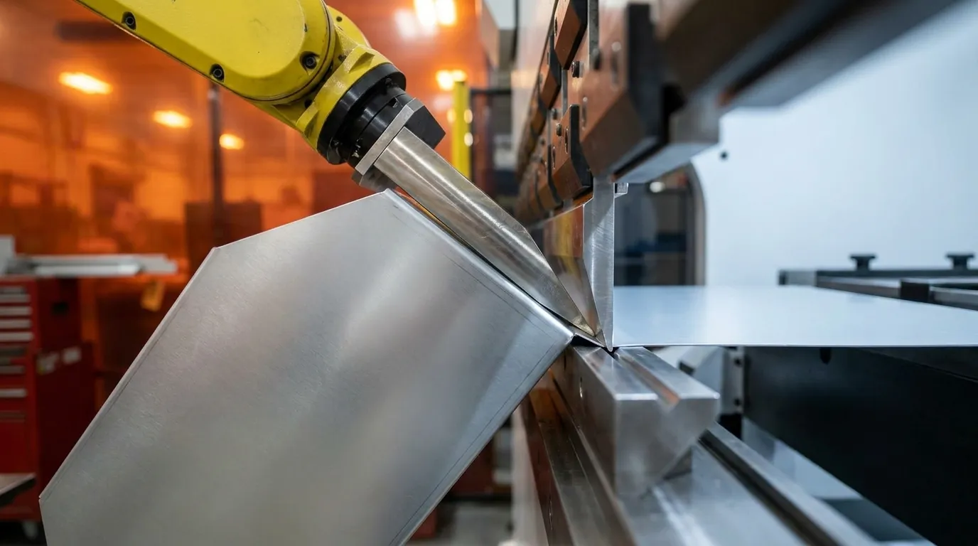
Bend reliefs are small cutouts placed at the end of a bend line where it meets a perpendicular edge or feature. Without reliefs, material stress concentrates at the corner during forming and causes tearing, distortion or cracking that propagates into adjacent features.
Relief width should match or exceed the material thickness. Relief depth should extend past the bend tangent line. Undersized reliefs are one of the most common sources of scrap on first-article runs. Consistent relief geometry also simplifies press brake setup and reduces operator-to-operator variation.
Hole-to-Bend Distance Control
Bend zone management also includes how holes and slots interact with formed regions. Holes, slots and cutouts placed too close to a bend line deform during forming. The bend zone pulls material inward, distorting the hole geometry and shifting its position relative to the design intent.
As a general practice, maintain a minimum distance from the edge of any hole or slot to the nearest bend tangent line. That minimum scales with material thickness and gauge. Thicker, harder materials require greater clearance. When a design requires a hole near a bend, consider relocating the feature to the flat blank or adding a relief slot to isolate the hole from the forming zone.
Hardware Strategy for Clinching Success
Self-clinching fasteners such as PEM nuts, studs and standoffs install under controlled press force. The sheet material flows into the fastener undercut and locks it in place. This process requires adequate material thickness, sufficient edge distance and a flat, unsupported surface at the insertion point.
Placing hardware too close to a bend, a weld seam or another fastener reduces the material support needed for proper clinching. When support is insufficient, the fastener can spin, pull out under load or seat at an angle. These failures stem from design decisions, so hardware strategy should be resolved during DFM review, not after first-article inspection.
Standardizing fastener families across the enclosure BOM reduces tooling setups, simplifies assembly instructions and lowers the risk of installation errors during mid-volume production runs.
Finish Considerations for Fit and Function
Once hardware placement is resolved, finish application becomes the next critical DFM topic. Powder coat and wet paint add measurable thickness to every coated surface. On mating panels, lid flanges and threaded hardware, that buildup affects fit and function. Clearance holes sized for bare metal may bind after coating. Thread engagement on coated hardware may fall short of specification.
DFM review for finish should address three connected decisions: clearance allowances on mating features, masking requirements for critical surfaces and hardware installation sequence before or after coating. Each decision affects the others because coating thickness, masking boundaries and installation timing determine whether the final assembly meets dimensional and cosmetic requirements. Screen printing and CARC or mil-spec coatings add further dimensional and adhesion considerations that must be specified in the drawing package before production begins.
Material and Gauge Reference for Forming
Material selection and gauge influence formability, springback and minimum bend radius. Cold-rolled steel offers good formability but can show springback at tighter radii. Stainless steel shows higher springback and work-hardens during forming. Aluminum 5052 is preferred for enclosures yet cracks if bent against grain. Galvanized steel requires radius control to maintain coating integrity at bends. Specific parameters should align with the fabricator tooling and material certifications.
Post-Bend Tolerance Reference for Assemblies
Post-bend tolerances build on material behavior and bend strategy. Feature type, achievable tolerance and stack-up risk vary with bend count and datum strategy. Single bend angles carry low stack-up risk when bend radius and tooling are specified in the drawing. Flange length and hardware position carry medium risk. Multi-bend assemblies carry high risk.
Mitigation includes referencing from a single datum face, reducing bend count and inserting hardware before forming where possible. Specific tolerances should align with the fabricator process capability data.
Common DFM Mistakes in Enclosure Design
- Designing to CAD defaults, not shop-floor tooling. Default bend radii in CAD software rarely match the press brake tooling available at the fabricator.
- Ignoring grain direction on aluminum. Bending aluminum parallel to the rolling direction increases crack risk at tight radii.
- Specifying tight tolerances on multi-bend parts without a datum strategy. Each bend adds variation. Without a clear reference datum, stack-up accumulates across the assembly.
- Omitting finish callouts from the drawing package. Fabricators cannot account for coating thickness, masking or hardware sequence without explicit finish specifications.
- Locking hardware locations before DFM review. Hardware positions that look correct in CAD often conflict with bend zones, weld access or assembly tooling on the floor. See the Hardware Strategy section for placement criteria.
Scaling DFM from Prototype to Production
DFM rules that work at 10 units do not automatically transfer to 200 or 500 units. Prototype runs often rely on manual adjustments, operator judgment and flexible fixturing that disappear at production volumes. Features that were hand-fitted at prototype become systematic defects at scale.
Scaling DFM requires reviewing press brake programs, punch tooling, weld fixtures and assembly work instructions against the production BOM, not the prototype BOM. Hardware standardization, bend sequence planning and finish masking plans all need to be locked before the first production run begins.
A vertically integrated partner that manages fabrication, finishing and assembly under one roof can identify scaling conflicts earlier. The same engineering team that reviews the prototype drawing also writes the production router and aligns it with quality requirements.
Request a quote to validate enclosure designs against Fabcon production tooling and processes.
DFM Collaboration Checklist for Enclosure Programs
The following checklist supports early-stage DFM collaboration between engineering teams and a fabrication partner operating under ISO 9001:2015 and AS9100D quality systems.
- Drawing package complete: 2D drawings with GD&T callouts, material specification, finish specification and hardware BOM submitted before quoting.
- Bend relief geometry confirmed: All interior corners reviewed for relief width and depth relative to material thickness.
- Hole-to-bend distances verified: All holes, slots and cutouts checked against minimum clearance for the specified gauge.
- Hardware locations reviewed: All self-clinching fastener positions checked for edge distance, material support and proximity to bend zones.
- Finish callouts specified: Coating type, thickness range, masking requirements and hardware installation sequence documented.
- Tolerance stack-up analyzed: Multi-bend assemblies reviewed for cumulative variation and datum strategy confirmed.
- Production process validated: Press brake programs, punch tooling and weld fixtures reviewed against production volume, not prototype volume.
- Quality and traceability requirements confirmed: Inspection criteria, first-article requirements and compliance documentation (ISO 9001:2015, AS9100D, UL, CSA) aligned with program regulatory obligations.
Fabcon in-house engineering and quoting teams conduct this review collaboratively with the customer technical team before production begins. The same quality management system that governs aerospace and defense programs applies to every enclosure program across all industries served.
Frequently Asked Questions
What is DFM for custom metal enclosures?
DFM for custom metal enclosures reviews a sheet metal design against the fabricator tooling, materials and processes before production. The goal is to identify and resolve features that would cause forming defects, tolerance stack-up, hardware failures or finish conflicts. DFM review typically covers bend geometry, hole placement, hardware strategy, finish specifications and tolerance analysis. Conducting DFM early reduces rework, scrap and program delays.
When should DFM review happen in the design process?
DFM review works best before the drawing package is finalized for production. Ideally, the fabrication partner reviews the design at the detailed design stage, when changes remain low cost. Waiting until first-article inspection to discover DFM issues shifts correction cost onto the production program. Early collaboration between the engineering team and the fabricator quoting and manufacturing engineers supports smooth transition from prototype to mid-volume production.
How does tolerance stack-up affect custom metal enclosure assemblies?
Every bend in a sheet metal part introduces dimensional variation. In a multi-bend enclosure, those variations accumulate across the assembly. If the datum strategy is not defined correctly, the cumulative error can cause panels to misalign, hardware to bind or lids to not close flush. Managing tolerance stack-up requires referencing critical dimensions from a single datum face, minimizing bend count where possible and confirming that the fabricator process capability matches the drawing tolerance requirements.
How does powder coat thickness affect enclosure fit?
Powder coat adds material to every coated surface, which can cause binding on mating flanges, reduced thread engagement and panel seating issues. DFM review for finish should specify the coating thickness range, identify surfaces that require masking and confirm whether hardware is installed before or after coating. These decisions protect both functional fit and cosmetic quality.
What is the difference between prototype DFM and production DFM?
Prototype DFM proves design geometry and fit. Production DFM validates repeatability at volume using production tooling and work instructions. See the Scaling DFM section for how features that work at prototype volumes can become systematic defects at scale.
How does working with a vertically integrated fabricator simplify DFM?
A vertically integrated fabricator manages fabrication, finishing and assembly under one roof. The engineering team reviewing the DFM drawing has direct visibility into the press brake tooling, the powder coat line and the assembly fixtures. DFM conflicts that would otherwise surface as vendor handoff problems, such as a finish specification that affects hardware installation or a bend geometry that conflicts with weld fixture access, are identified and resolved within a single program team. For programs governed by ISO 9001:2015 or AS9100D quality systems, this integration also simplifies traceability and inspection documentation across the full build.
Request a quote to identify integration conflicts before they appear as vendor handoff issues.