

Last updated: August 14, 2026
Key Takeaways
- Standardized bend radii that match press-brake tooling remove specialty tooling orders and extra setups, which cuts cost and lead time.
- Correct K-factors, hole-to-bend clearances and modeled corner reliefs prevent dimensional errors, deformed features and material tearing before cutting starts.
- Functional datums, baseline or ordinate dimensioning and targeted tolerances reduce cumulative error, inspection effort and first-article rejections.
- Grain direction, finish thickness and submission of both the 3D model and flat pattern support accurate quoting and prevent post-finish rework or quoting delays.
- Early DFM collaboration with Fabcon validates tooling, clearances and tolerances in one review, which shortens the path from design to production.
Ranked CAD DFM Checklist for Sheet Metal
The following 12 habits are ranked by impact on cost and lead time. Each habit focuses on a specific CAD decision that affects manufacturability and provides a clear action, a fabrication constraint and a before-and-after example.
-
Habit 1: Match Bend Radius to Press-Brake Tooling
CAD action: Replace software default radii with a value tied to the fabricator punch library. A bend radius equal to material thickness often forces specialty tooling.
Fabrication constraint: Minimum inside bend radii vary by alloy: 0–0.5×T for mild steel, 0.5–1.0×T for stainless and 1.0–1.5×T for aluminum, where T is material thickness.
Before/after: A model with a 0.5 mm radius on 2 mm stainless triggers a specialty punch order and a re-quote. The same model revised to a 2–3 mm radius runs on standard tooling and holds schedule.
Fabcon engineering checks punch availability during quoting so production starts on known tooling.
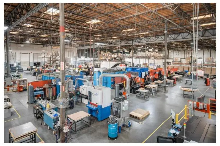
Founded in 1977, Fabcon runs 220,000 sq ft of vertically integrated fabrication across two Southern California facilities — engineering, machining, fabrication, finishing, and assembly under one roof. Habit 2: Use One Bend Radius Across the Part
CAD action: Audit every bend in the model and normalize to one inside radius value. Each different radius requires a separate punch, which increases setup time and cost.
Fabrication constraint: Matching all inside radii to a single value allows one punch and die set to handle every bend, which removes tool changes and cuts setup time.
Before/after: A chassis with three different radii needs three setups. The same chassis with one unified radius runs in a single press-brake program with one setup.

A U.S.-based partner since 1977 — Fabcon combines the infrastructure of a large contract manufacturer with the responsiveness and made-in-America accountability of a specialist. A unified-radius model lets Fabcon price the part in one pass and return a quote with fewer clarification cycles.
Habit 3: Store Verified K-Factors in the Bend Table
CAD action: Replace generic software K-factors with values matched to the alloy, temper, die opening and bend radius. Library values that work for one material and press brake may not match another setup, so K-factors should serve as a design starting point and then be confirmed with the fabricator before production.
Fabrication constraint: K-factors typically range from 0.3 to 0.5 depending on material. An incorrect K-factor produces inaccurate flat patterns and cumulative dimensional errors after multiple bends.
Before/after: A flat pattern generated with a default K-factor of 0.50 on hard-temper aluminum produces a part that is off after forming. Corrected K-factor data aligns the flat pattern with the formed part before cutting begins.
Early collaboration with Fabcon process engineers aligns CAD bend data with production tooling so first-run parts match the model.
Habit 4: Keep Holes and Inserts Clear of Bend Lines
CAD action: Move holes, slots and PEM inserts away from bend tangent lines. Keep the edge of noncritical holes at least R + 2T from the bend tangent. Critical features may need more clearance, reliefs or post-bend operations.
Fabrication constraint: Holes, slots and PEM inserts placed too close to the bend tangent line deform during forming.
Before/after: A mounting hole placed 1×T from a bend tangent elongates during forming and fails assembly fit. Moving it to R + 2T preserves geometry and passes inspection.
Fabcon DFM reviews flag hole-to-bend clearance issues in the model so first-article parts pass without rework.
Habit 5: Model Corner Reliefs at Bend Intersections
CAD action: Add relief cuts at the ends of any bend that does not run the full sheet width. Relief cuts must be at least as wide as material thickness to prevent tearing and first-article rejection.
Fabrication constraint: Without reliefs, material tears at intersecting bend lines, which produces scrap and forces design changes after programming.
Before/after: A bracket with no corner reliefs tears at the flange intersection on the first press run. Added modeled reliefs remove the tear and eliminate a manual deburring step.
Models that include reliefs allow Fabcon to quote the true process without padding for manual corrections.
Habit 6: Standardize Hole Diameters to Common Tools
CAD action: Select hole diameters from the fabricator standard punch library. Each cutting process has a minimum practical diameter based on material thickness.
Fabrication constraint: Nonstandard diameters require custom punches or laser-only processing, which adds cost and lead time to every run.
Before/after: A panel with seven unique hole diameters needs seven punch setups or full laser processing. Rationalizing to three standard sizes cuts setups and shortens cycle time.
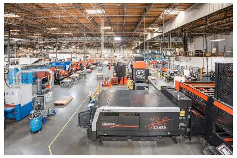
Precision starts at the cut. In-house laser cutting delivers tight-tolerance blanks with the speed and repeatability that high-mix, infrastructure-grade programs demand. Fabcon engineering supplies a standard tooling list during early collaboration so CAD hole libraries align with shop tools.
Habit 7: Build Dimensions Around Functional Datums
CAD action: Anchor critical dimensions to datums that match physical, inspectable surfaces used to fixture the part. Select large, stable features that can be probed or clamped easily during manufacturing.
Fabrication constraint: Dimensioning from functional datums instead of chaining across multiple bends reduces cumulative error and supports consistent inspection.
Before/after: A drawing that chains five dimensions across three bends accumulates tolerance error at the final feature. Resetting dimensions to a single formed datum removes the stack-up.
Fabcon inspection uses the same datum scheme defined in CAD, which ties design intent directly to quality records.
Habit 8: Use Baseline or Ordinate Dimension Schemes
CAD action: Replace chain dimensioning with baseline or ordinate schemes on sheet metal drawings. Baseline and ordinate schemes avoid cumulative error and support predictable CNC programming.
Fabrication constraint: Chain dimensions compound tolerance across features, which makes inspection ambiguous and increases first-article risk.
Before/after: A laser-cut panel dimensioned with a chain scheme produces a hole pattern that drifts across the part. The same panel dimensioned from a single origin holds position across all features.
Ordinate-dimensioned drawings let Fabcon generate routers with less interpretation, which shortens quoting and planning time.
Habit 9: Tolerance Only Features That Affect Function
CAD action: Review every toleranced dimension and confirm that it mates, seals, carries load or affects assembly. Reserve tight tolerances for functional interfaces and critical mating surfaces and apply standard commercial bands to cosmetic or nonmating features.
Fabrication constraint: Laser-cut features can hold tighter bands than formed features. Applying the same tolerance to both creates unnecessary inspection work.
Before/after: A cosmetic panel with tight tolerances on every dimension requires full inspection of every feature. Relaxing nonfunctional dimensions to commercial bands removes inspection overhead without affecting fit or function.
DFM reviews with Fabcon separate functional dimensions from cosmetic ones so drawings carry only the tolerances that matter.
Habit 10: Align Bends Perpendicular to Grain Direction
CAD action: Mark grain direction on the flat pattern and orient bends perpendicular to that direction. Perpendicular bends produce more consistent results and lower cracking risk than bends parallel to the grain, especially for hard-temper aluminum, high-strength steel and small radii.
Fabrication constraint: Bends across the grain are the first to crack, especially in aluminum.
Before/after: A 6061-T6 bracket bent parallel to the grain cracks at the bend line on the first press run. Rotating the flat pattern 90 degrees removes the crack without changing geometry.
Fabcon engineering reviews grain orientation during DFM so material orders and nests support the intended bend direction.
Habit 11: Include Finish Thickness in Clearance and Fit
CAD action: Add finish allowance to clearance gaps, tab-and-slot joints and mating surfaces in the model. Powder coating adds thickness per side and must be included in clearance and fit calculations for assemblies and hinges.
Fabrication constraint: Parts designed to bare-metal tolerances bind or show gaps after finishing, which forces rework or design changes after production starts.
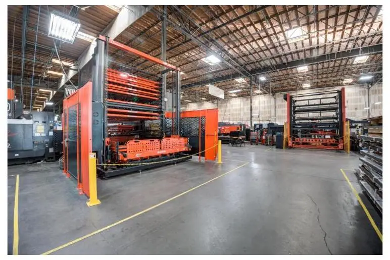
In-house finishing — powder coat, wet paint, silkscreen, and CARC mil-spec coating — keeps cosmetic standards consistent and removes a supplier handoff from the build. Before/after: A tab-and-slot enclosure designed to bare-metal clearance binds after powder coat. Added finish allowance in CAD produces a correct fit off the line.
Fabcon manages fabrication and finishing in one facility, so engineering applies correct finish allowances during DFM and prevents post-finish rework.
Habit 12: Send Both the 3D Model and Flat Pattern
CAD action: Export and submit the formed 3D model with the flat pattern, including bend sequence, bend direction symbols and noted K-factor. Providing both files prevents quoting delays caused by recreating flat patterns or guessing thickness, bend radius and bend allowance.
Fabrication constraint: Multi-bend parts should carry numbered bends and standardized up or down symbols relative to the flat pattern reference plane.
Before/after: A model submitted without a flat pattern forces the fabricator to reconstruct bend allowances, which slows the quote. A complete package with 3D model, flat pattern and bend table supports fast, accurate pricing.
Fabcon quoting teams move complete model packages through review faster, which shortens the time from inquiry to first article.
Summary Table of Sheet-Metal CAD Habits
Habit Primary Cost Driver CAD Feature or Setting to Check 1. Set bend radius to tooling Specialty tooling orders Bend radius value in sheet metal feature 2. Unify all bend radii Multiple press-brake setups Bend radius audit across all features 3. Store correct K-factors Flat pattern dimensional error Gauge table or bend table K-factor field 4. Maintain hole-to-bend clearance Deformed holes, rework Hole-to-bend distance check 5. Add corner reliefs Tearing, scrap Relief cut at every bend intersection 6. Standardize hole diameters Custom punch orders Hole diameter library vs. standard punch list 7. Apply functional datum strategy Inspection ambiguity, rework GD&T datum callouts A, B, C 8. Use baseline/ordinate dimensioning Cumulative tolerance error Dimension scheme in drawing template 9. Tolerance only functional features Excess inspection cost Tolerance audit per feature function 10. Orient bends to grain Cracking, scrap Grain direction mark on flat pattern 11. Account for finish thickness Post-finish rework Clearance and fit gaps in mating features 12. Submit 3D model and flat pattern Quoting delays, re-quotes Export checklist: 3D model, flat pattern, bend table Downloadable DFM Checklist for CAD Reviews
Copy the following checks into a CAD workflow or design review template. Each item maps directly to one of the 12 habits above.
- Bend radius set to fabricator punch library value
- All bend radii unified to a single value across the part
- K-factor confirmed against alloy, temper and die opening
- All holes and slots at least R + 2T from bend tangent lines
- Corner reliefs modeled at every bend intersection
- All hole diameters selected from standard tooling library
- Datums assigned to large, physically inspectable surfaces
- Baseline or ordinate dimensioning applied to all drawings
- Tight tolerances limited to mating, sealing and load-bearing features only
- Grain direction marked on flat pattern and bends oriented perpendicular
- Finish allowance added to all clearance gaps and mating surfaces
- 3D model, flat pattern and bend table submitted together
Fabcon ISO 9001:2015 and AS9100D quality frameworks provide the traceability backbone that links each checklist item to a documented production record across fabrication, finishing and light electromechanical assembly. Every part built at Fabcon carries a quality trail from raw material to shipped assembly.
Conclusion: Turning CAD Habits Into Production Results
The 12 habits above remove specific failure modes from the sheet metal design-to-manufacture path. Applied together, they support accurate quotes, first-article success and repeatable production without rework.
The checklist delivers the strongest results when paired with early collaboration. Fabcon engineering and quoting teams review models before production, confirming tooling availability, datum schemes, tolerance choices and finish allowances in a single DFM pass. That review aligns design intent with shop-floor reality before any sheet is cut.
Get a quote and connect with Fabcon engineering at the start of the design cycle.
Frequently Asked Questions
Most Common CAD Issue Behind Sheet Metal Quoting Delays
Submitting a model without a flat pattern is the most frequent cause of quoting delays in sheet metal fabrication. When a fabricator receives only a formed 3D model, the quoting team must reconstruct bend allowances, verify K-factors and recreate the flat pattern before pricing. That reconstruction takes time and introduces assumptions that may not match the design intent. Submitting the formed 3D model with the flat pattern, bend sequence, bend direction symbols and K-factor allows direct quoting from the file package. Fabcon quoting teams process complete submissions faster and with fewer clarification rounds, which shortens the time from inquiry to approved quote.
How Early DFM Collaboration Reduces First-Article Failures
First-article failures often trace to three sources: bend radii that do not match available tooling, hole or slot features placed inside the deformation zone near a bend and tolerances that exceed forming capability. Each issue appears in the CAD model before material is cut. When an engineer shares the model with a fabricator engineering team at the design stage, those issues become CAD edits instead of scrapped parts. Fabcon engineering and quoting teams review models before production, confirming tooling availability, clearance compliance and tolerance achievability in a single DFM pass. That early review converts potential first-article failures into low-cost pre-production corrections.
Why Multiple Bend Radii Increase Fabrication Cost
Every unique inside bend radius on a sheet metal part requires a dedicated punch and die set. A part with three different radii needs three separate press-brake setups, each with a tool change, alignment check and test bend. Setup time is nonproductive time and compounds across production runs. Normalizing all bends to a single radius value allows the press-brake operator to run the entire part on one tool set in one program. The cost impact is direct because fewer setups mean less labor per part and shorter production cycles. Fabcon engineering identifies radius inconsistencies during DFM and recommends a unified value that matches standard tooling.
Practical Tolerance Strategies for Sheet Metal Parts
An effective tolerance strategy in sheet metal design applies tight callouts only where fit, function, sealing or load transfer require them and leaves other dimensions at standard commercial bands. Tight tolerances on nonfunctional features add inspection steps, slow production and increase rejection risk without improving performance. A practical review asks what happens if a feature sits at the loose end of its tolerance. If the answer is no meaningful change, the tolerance can be relaxed. Laser-cut features hold tighter bands than formed features, so a single tolerance scheme across both processes often creates unnecessary inspection work. Fabcon engineering conducts tolerance audits during DFM, highlighting which callouts are functionally justified and which can be relaxed.
Fabcon Quality Certifications and Their Impact on Programs
Fabcon holds ISO 9001:2015 and AS9100D certifications and is ITAR registered. ISO 9001:2015 defines the quality management system that governs process consistency, corrective action and supplier controls across fabrication, finishing and assembly. AS9100D adds aerospace-specific requirements for risk management, configuration control and full traceability. Together, these frameworks ensure that every part produced at Fabcon carries a documented quality trail from raw material receipt through final shipment. For engineering teams in regulated industries such as aerospace, defense, medical devices and energy infrastructure, that traceability supports regulatory compliance and liability management. It also provides the data needed for first-article inspection reports and ongoing production audits.