Last updated: April 17, 2026
Key Takeaways
- Apply DFM rules like 2T+R hole-to-bend spacing and standard gauges to cut costs and avoid redesigns in precision sheet metal fabrication.
- Use laser cutting for ±0.005″ tolerances with minimal kerf, and switch to waterjet for heat-sensitive materials to prevent distortion.
- Use the bend allowance formula BA = (π/180) * A * (R + K*T) and program overbend to counter springback for accurate forming.
- Adopt robotic welding and vertically integrated production to improve repeatability, shorten lead times, and scale from prototype to mid-volume.
- Partner with Fabcon for a DFM consultation to refine your precision sheet metal project with full traceability and U.S.-based manufacturing.
Step 1: Build Strong CAD/CAM and DFM Foundations
Design-for-manufacturability sets up every downstream sheet metal process for success. Effective DFM can significantly reduce manufacturing costs and prevent late-stage redesigns. One core rule is maintaining 2T + R (two times material thickness plus bend radius) hole-to-bend spacing for holes under 25mm to avoid distortion during forming. Standard gauge thicknesses improve material availability, simplify purchasing, and reduce lead times.
Essential DFM checklist items work together to prevent failures and control cost. Specify bend radii equal to or greater than material thickness to reduce cracking during forming. Limit complex cutouts that increase deformation risk when parts are bent. Avoid tight inside corners that concentrate stress and can cause premature failure. Apply tight tolerances only to dimensions that drive function so you control cost while still protecting performance. Tools like SolidWorks sheet metal modules embed these rules directly into your CAD workflow and flag issues before release.
Step 2: Achieve Precision Cutting with Laser and Waterjet
Modern laser cutting delivers high accuracy for thin and medium-gauge materials. High-quality fabrication shops routinely hold ±0.005 inches on thin sheet. CO2 laser kerf width typically ranges from 0.008″ to 0.020″ (0.2-0.5mm), and fiber lasers produce even cleaner edges with smaller heat-affected zones.
Cutting strategy depends on how the laser beam behaves through the material. Minimum hole size usually matches the material thickness, and this rule becomes harder to meet as thickness increases because beam taper grows. That taper explains why materials under 3mm generally hold tighter tolerances than thicker plate, where the beam loses focus through the depth. For parts that cannot tolerate any heat-affected zone, waterjet cutting offers a cold process that avoids thermal distortion entirely.
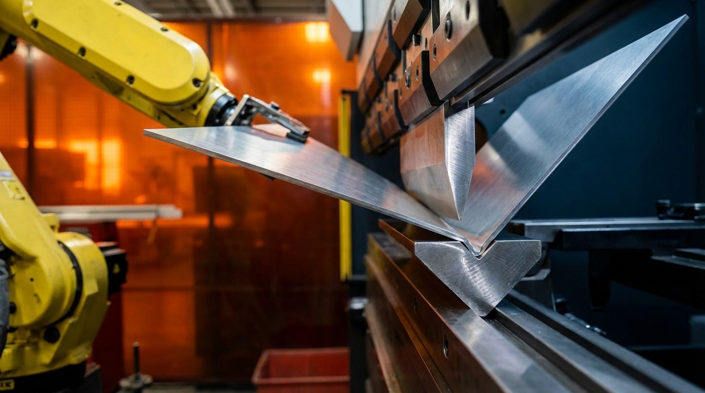
Step 3: Use Advanced Bending and Forming Techniques
Accurate forming depends on correct bend allowance calculations and a clear understanding of material behavior. The core formula is BA = A * (π/180) * (R + K * T), where A is bend angle in degrees, R is inside radius, K is K-factor (often 0.33 to 0.5), and T is material thickness. Springback can introduce about ±1° of variation, so CNC programs usually include overbend compensation to hit the final angle.
The 3-4-5 squareness method provides a quick check on bend accuracy. Measure 3 units along one leg, 4 units along the perpendicular leg, and confirm the diagonal measures exactly 5 units. The table below shows how typical K-factors and radii translate into 90° bend allowances for common materials and thicknesses.
| Material/Thickness | Inside Radius | K-Factor | 90° Bend Allowance |
|---|---|---|---|
| Mild Steel 1.0mm | 1.0mm | 0.33 | 2.09mm |
| Mild Steel 2.0mm | 2.0mm | 0.33 | 4.18mm |
| Aluminum 1.0mm | 1.0mm | 0.40 | 1.50mm |
| Stainless 2.0mm | 2.0mm | 0.35 | 4.24mm |
Step 4: Apply Robotic Welding and Joining for Consistency
Automation now plays a central role in sheet metal welding, forming, and handling. The industry is attacking the welder and operator shortage through both general-purpose and specialized robots. Tesla’s Optimus Gen 3 humanoid robots show how flexible automation can handle sheet metal payloads up to 45 pounds with 22 degrees of freedom in each hand.
Specialized systems focus on specific fabrication tasks. Amada’s CR-010B Collaborative Robot, launched in July 2025, simplifies programming for press brake operations and removes the need for complex CAM software. Growth in automated metal forming equipment reflects how these solutions expand capacity while easing labor constraints. Together, these systems support 24/7 lights-out manufacturing with consistent weld quality and reduced dependence on manual labor.
Step 5: Streamline Finishing and Electromechanical Assembly
Integrated finishing and assembly keep parts flowing instead of waiting at external vendors. In-house powder coating, wet paint, and screen printing provide consistent surface preparation and coating thickness under one quality system. A key detail is coating buildup: powder coating usually adds 0.002 to 0.005 inches, so designers must adjust hole sizes and mating features accordingly.
Electromechanical assembly integration brings fabricated enclosures, wiring, hardware insertion, and component mounting into a single operation stream. This approach reduces coordination complexity by removing multi-vendor communication, which directly shortens lead times and creates clear accountability for complete assemblies. Quality systems then track both mechanical tolerances and electrical performance through every stage of the combined process.
Step 6: Use CMM Inspection and Quality Control Matrices
Coordinate Measuring Machines verify that fabricated parts meet geometric dimensioning and tolerancing requirements. Quality programs rely on micrometers accurate to 0.0001 inches for key dimensions and CMMs for complex geometries and datums. CMM verification confirms the ±0.005-inch cutting and forming tolerances discussed earlier and documents actual results for traceability.
Different industries demand different tolerance bands based on risk and function. Medical device assemblies often require about ±0.005mm to ±0.01mm on critical features, while non-critical dimensions may relax to around ±0.05mm. EV components need similar precision on battery housings and electrical interfaces to ensure sealing and connectivity. Data center rack structures can usually accept standard process tolerances near ±0.1mm, yet still call for roughly ±0.02mm on mounting hole patterns so servers and accessories align correctly.
Step 7: Scale from Prototype to Mid-Volume Production
Agile production cells allow programs to grow without the rigid constraints of large contract manufacturers. About 69% of U.S. manufacturers report reshoring supply chains with positive results, driven by resilience goals and closer collaboration with engineering teams. Fabcon’s cellular manufacturing model supports this shift by adapting to changing volumes, mixed SKUs, and evolving bills of materials.
This flexibility benefits high-growth companies that need rapid scaling without high minimums or long onboarding typical of global suppliers. Process consistency remains the anchor as programs change. Documented work instructions, standardized tooling, and cross-trained teams keep quality stable while capacity and product mix evolve.
Step 8: Troubleshoot Deformation and Misalignment Systematically
Structured troubleshooting prevents recurring defects, rework, and schedule slips. Typical issues include bend angle variation from springback, hole distortion near bend lines, and assembly misalignment from stacked tolerances. Apply the 3-4-5 squareness check described earlier to confirm perpendicularity before moving parts into assembly. Weld repeatability depends on consistent joint preparation, stable fixturing, and tightly controlled parameters.
The table below connects common fabrication failures to likely causes and practical correction methods so teams can respond quickly and consistently.
| Issue | Likely Cause | Correction Method |
|---|---|---|
| Bend Angle Variation | Material springback | Program overbend compensation in CNC |
| Hole Distortion | Hole placed too close to bend line | Increase hole-to-bend spacing per DFM guidelines or relocate holes farther from bend |
| Weld Cracking | Excessive constraint from small bend radius | Increase bend radius to at least 1T |
Why Fabcon Excels in Precision Sheet Metal Mastery
Fabcon combines deep experience with fully integrated U.S. manufacturing to support demanding sheet metal programs. Founded in 1977, the company operates 220,000 square feet of vertically integrated facilities with ISO 9001:2015, AS9100D, and ITAR certifications. Many job shops stop at basic sheet metal, and large contract manufacturers often require high minimum volumes. Fabcon fills the gap by offering sophisticated infrastructure with the agility needed for mid-volume and growth-stage programs.
The operation spans laser cutting, CNC forming, robotic welding, machining, powder coating, and electromechanical assembly in one connected workflow. This structure removes vendor transfers that commonly add 1 to 3 weeks to lead times and keeps quality consistent from prototype through production. Recent work includes precision data center rack assemblies and EV charging components that demand tight tolerances and full traceability. Get a fast quote for your next precision fabrication project.
Conclusion
Successful precision sheet metal fabrication depends on strong design practices, accurate cutting, reliable bending calculations, smart automation, integrated finishing, rigorous quality control, scalable production, and disciplined troubleshooting. The 2026 manufacturing environment emphasizes reshoring, automation, and supply consolidation, with U.S. manufacturers announcing 150,206 reshoring jobs in 2023 and continuing to invest in domestic capacity. AI-driven CAM tools and collaborative robots are reshaping traditional workflows while still relying on proven fabrication fundamentals.
Manufacturers that pair technical mastery with the right partners gain a clear advantage. Vertically integrated providers can manage complex assemblies, maintain consistent quality, and deliver on tight schedules. With more than 45 years of experience and comprehensive in-house capabilities, Fabcon is positioned to support demanding precision sheet metal and electromechanical projects. Request a quote for your project and see how true vertical integration improves speed, quality, and reliability.
Frequently Asked Questions
How does vertical integration cut lead times in sheet metal fabrication?
Vertical integration keeps cutting, forming, welding, finishing, and assembly inside one coordinated operation. When a single team manages scheduling and quality across all steps, typical lead times drop by 1 to 3 weeks compared with juggling multiple suppliers. This structure also removes coordination delays and eliminates quality disputes between vendors. Fabcon’s integrated model supports fast prototype-to-production transitions and responsive engineering changes.
What tolerances can precision sheet metal fabrication hold for medical assemblies?
Modern precision sheet metal operations can hold ±0.005 inches for laser cutting and CNC forming, with ultra-precision features reaching about ±0.0005 inches when required. Medical device assemblies often need ±0.005mm to ±0.01mm on critical dimensions, supported by full traceability and CMM inspection. The most effective approach applies tight tolerances only where function demands them and uses standard bands elsewhere to control cost. Material choice, tooling condition, and process stability all influence the final achievable precision.
How can I improve accuracy in sheet metal assemblies?
Assembly accuracy starts with controlling tolerance stack-up at each fabrication step. Use the 3-4-5 squareness method to confirm bend perpendicularity, maintain minimum hole-to-bend spacing of 2T plus bend radius, and standardize fixturing for welded assemblies. DFM practices such as standard bend radii and thoughtful tolerance allocation reduce downstream fit issues. CMM checks at key stages verify dimensions before you commit parts to final assembly.
What are the most effective sheet metal bending techniques?
Air bending offers flexibility, lower tonnage requirements, and adjustable radii, which makes it ideal for prototypes and small batches. Bottoming provides more consistent angles with reduced springback, so it suits higher-volume runs. Coining delivers the highest precision and minimal springback but demands the most tonnage and robust tooling. K-factors usually fall between 0.33 and 0.5 depending on material and method, with air bending often producing lower K-factors because of localized strain. Choose the method based on required precision, volume, and material behavior.
How do I choose the right cutting process for my application?
Laser cutting works best for thin to medium materials that need ±0.005 inch tolerances, minimal heat-affected zones, and clean edges. Waterjet cutting suits thick sections or heat-sensitive alloys because it introduces no thermal distortion. Plasma cutting offers a cost-effective option for heavier structural parts where ±0.020 inch tolerances are acceptable. Consider thickness, tolerance targets, edge quality, and production volume when selecting your cutting process.
How does design-for-manufacturability reduce rework in sheet metal fabrication?
DFM practices can lower manufacturing costs by 20 to 50 percent by eliminating design issues before production. Early collaboration on bend radii, hole placement, tolerance strategy, and material selection prevents redesigns and schedule slips. Standard gauge choices improve availability and shorten lead times. Proper hole-to-bend spacing avoids distortion during forming. The most effective programs involve manufacturing experts during design instead of waiting until tooling and production are already in place.