
Key Takeaways
- Metal cabinet tolerances span flat blanks, bends, holes and final assembly, and they directly affect fit, function and cost.
- Laser cutting, press brake forming and hardware insertion each introduce specific tolerance ranges that require consistent datums and sound DFM practices.
- Material gauge, grade and finishing processes shape achievable bend angles, flatness and assembled squareness in precision enclosures.
- Early tolerance stack analysis, GD&T application and first-article inspection reduce misalignment risk and costly rework in multi-panel cabinet programs.
- Partner with Fabcon for vertically integrated fabrication, finishing and assembly that delivers consistent tolerances across data center, energy storage and EV infrastructure projects. Start your project today.
Flat-Part Tolerances in Laser-Cut and Punched Cabinet Blanks
Laser cutting and CNC punching produce flat cabinet blanks that set the foundation for every downstream operation. Laser cutting achieves tight edge tolerances and handles complex contours without tooling changes. CNC punching suits high-repeat hole patterns but introduces a small amount of edge rollover that can affect downstream assembly fit.
Linear dimensional tolerances on flat parts fall in a narrow range for laser-cut components. Punched parts run slightly wider because tooling condition and material hardness introduce additional variation. Regardless of cutting method, edge-to-hole relationships stay tighter when a single datum strategy is applied consistently across the program.
Gauge affects achievable flatness directly. Thinner gauges are more susceptible to thermal distortion during laser cutting. Heavier gauges introduce residual stress that can cause bow or twist after blanking. These flatness issues carry into bending and assembly steps, so flatness must be verified before forming begins.
Data center enclosures and EV infrastructure cabinets rely on repeatable rack-mounting interfaces with consistent hole patterns. For these applications, laser cutting with a consistent datum scheme is the standard approach. Early DFM review of hole-to-edge relationships prevents tolerance stack issues before tooling is committed.
Bend Angle and Radius Rules for Press Brake Cabinet Panels
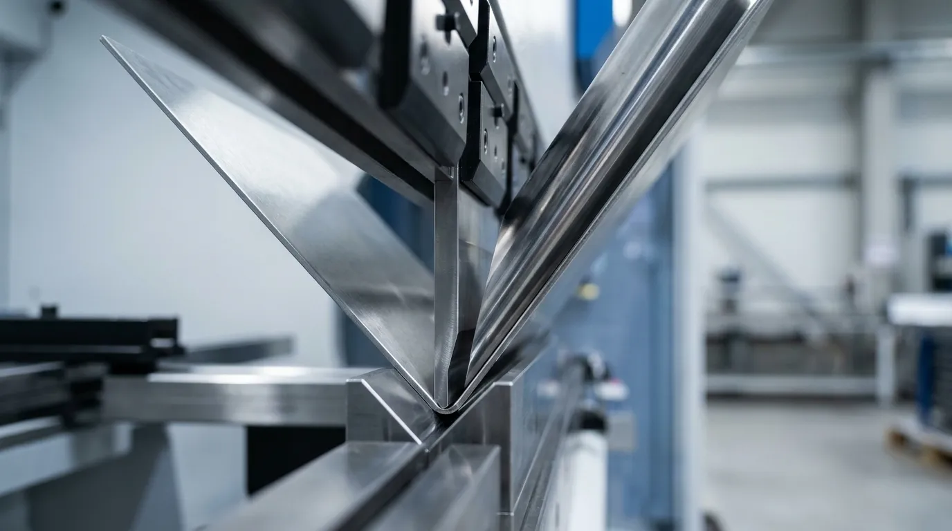
Once flat blanks meet dimensional specifications, press brake forming introduces angular and positional variation that compounds across every bend in a cabinet panel. Air bending used in most industrial applications sets bend angle by punch penetration depth rather than die geometry, which makes final angular tolerance sensitive to material springback and thickness variation.
Industrial-grade CNC press brakes support tight angular and dimensional tolerances for precision enclosures such as electrical cabinets and server racks. Standard press brake bends achieve consistent tolerances across a range of common sheet metal materials when tooling and setup remain stable.
Bottoming delivers higher angular accuracy and reduced springback than air bending by forcing the sheet to conform fully to the die walls. This method requires higher bending force and careful tooling selection. For cabinet programs that demand consistent door-frame geometry, bottoming or coining is specified at critical flanges.
Standard practice for sheet metal enclosure design uses an inside bend radius equal to material thickness to maintain structural strength and avoid failure points. Tighter radii increase stress concentration, and high-strength or work-hardened materials bent below this standard can crack at the bend zone, especially when grain direction and K-factor are not accounted for in flat-blank calculations.
Energy storage enclosures and medical device carts often rely on multi-bend panels that must align to mating frames. For these programs, bend-line location tolerances must be specified on the drawing and verified with first-article inspection before production release.
Hole and Hardware Tolerances for Reliable Cabinet Assembly
Hole position tolerances determine whether PEM fasteners, hinges, rack rails and panel hardware align across mating parts. True-position tolerances for laser-cut holes fall in a narrow range that depends on part size and the number of bends between the datum and the feature.
Hardware insertion with PEM nuts, studs and standoffs adds a press-in positional variation that belongs in the tolerance budget. Mislocated hardware is a primary cause of assembly misalignment in multi-panel cabinets. Specifying hardware insertion as part of the fabrication scope rather than a separate operation removes one handoff and one source of variation.
Reducing welding where possible and using features such as PEM inserts improves assembly efficiency and lowers misalignment risk in sheet metal enclosures. For traffic safety and EV infrastructure cabinets that require field-replaceable panels, PEM hardware tolerances must be tight enough to allow blind assembly without adjustment.
Assembled Cabinet Dimensions and Squareness Standards
Assembled cabinet tolerances reflect the cumulative effect of every upstream variation, including flat-part accuracy, bend-line location, weld distortion and fixturing. Overall assembled dimensions for precision enclosures hold a controlled range on major dimensions. Squareness measured as the difference between diagonal dimensions follows a consistent standard per frame length.
Weld sequence and fixturing serve as the primary controls for assembled squareness. Tack welding in a dedicated fixture before full-penetration passes limits distortion that can pull frames out of square. For cabinets with close-tolerance door openings, post-weld dimensional inspection is standard before finishing operations begin.
Tolerance stack analysis at the assembly level is essential for programs with multiple mating enclosures such as battery storage arrays or modular data center racks. Each individual part tolerance contributes to assembled variation. Without a stack analysis, interference fits and misaligned bus connections become common failure modes.
Standard Gaps, Door Reveals and Flushness in Cabinet Arrays
The standard gap between adjacent metal cabinets in rack or array configurations provides clearance for thermal expansion, finishing thickness and installation variation. Tighter gaps require tighter upstream tolerances and increase the risk of paint or powder coat interference.
Door reveal, the visible gap between a door panel and its frame, is specified at a uniform distance around the perimeter. Achieving a consistent reveal requires a door frame that stays square within the assembled cabinet tolerance and hinge hardware located accurately relative to the door opening.
Surface flushness between adjacent panels or between a door face and a cabinet side is held to a controlled range. Flushness outside this range is visible to the eye and often triggers cosmetic rejection for medical device enclosures and data center infrastructure where appearance standards form part of the product specification.
How Gauge and Material Shape Cabinet Tolerances
Material thickness is the dominant variable in bending force calculations because tonnage rises sharply with thickness. This behavior directly affects whether a target bend angle can be formed repeatably. Heavier gauges require more force, produce more springback variation and are harder to hold to tight angular tolerances without bottoming or coining.
Material grade interacts with gauge to determine achievable tolerances. Cold-rolled steel holds tighter tolerances than hot-rolled steel due to its more consistent thickness and surface condition. Stainless steel springback is higher than mild steel and requires overbend compensation that must be dialed in per material lot. For heat-managed cabinets, aluminum may be preferred when passive heat dissipation matters, but thermal expansion must be accounted for in joints and tolerances, especially in high-heat applications.
Material selection for sheet metal enclosures should follow the operating environment and application. Cost, corrosion resistance, thermal properties and exposure conditions all affect the trade-off. Specifying material grade and gauge early in the design process rather than leaving it open on the drawing prevents tolerance surprises during first-article inspection.
Production Factors That Control Cabinet Tolerances
Several production factors determine whether a cabinet program holds its specified tolerances consistently across a run.
Part complexity and bend count. Each additional bend adds positional variation to downstream features. Cabinets with multiple bends per panel require careful tolerance stack analysis to keep assembled dimensions within specification.
Tooling condition and setup. Worn punch tooling and inconsistent press brake setup are leading causes of tolerance drift in production. Preventing this drift requires calibrated tooling and documented setup procedures as prerequisites for repeatable results.
Fixturing and weld sequence. Welded assemblies without dedicated fixtures produce inconsistent squareness. Controlled weld sequences reduce distortion and improve repeatability across production lots.
Finishing thickness. Powder coat and wet paint add measurable thickness to mating surfaces. Door gaps and panel clearances must account for finish build-up to prevent interference after finishing.
Inspection and first-article verification. Prototyping sheet metal enclosures with laser cutting and CNC bending before mass production allows evaluation of material selection, assembly fit and thermal management without risking damage to stamping tools from design changes. First-article inspection against a full GD&T drawing confirms that production processes are capable before volume release.
DFM Checklist for Production-Ready Cabinet Drawings
The following checklist reflects the DFM principles discussed throughout this article. Addressing these items before releasing drawings reduces rework and shortens the path from prototype to production.
- Specify material grade, temper and gauge on the drawing and avoid leaving material open.
- Apply GD&T with a consistent datum scheme referenced from a single corner or edge.
- Set tighter tolerances only where assembly fit requires them. Unnecessary tightness increases manufacturing difficulty and cost.
- Specify inside bend radius equal to material thickness as the default. Tighter radii require engineering review.
- Include bend relief at all internal corners to prevent tearing.
- Locate holes and hardware a minimum of two times material thickness from any bend line.
- Specify hardware insertion PEM type, size and orientation on the fabrication drawing, not only the assembly drawing.
- Account for finish build-up in door gap and panel clearance dimensions.
- Identify squareness requirements on the assembly drawing with a diagonal tolerance callout.
- Conduct a tolerance stack analysis for any multi-panel or multi-enclosure array before releasing for production.
- Reduce the number of individual parts where possible to lower sourcing complexity, assembly error risk and quality-control time.
Engineering and procurement teams working on precision cabinet programs can engage Fabcon’s DFM team before drawings are finalized. Connect with our DFM team to start the conversation early.
Frequently Asked Questions
What is the standard gap between metal cabinets in a rack or array installation?
As noted earlier, standard gaps account for thermal expansion and finish build-up. Tighter gaps are achievable but require tighter upstream fabrication tolerances and careful finish specification to prevent interference after coating.
What causes metal cabinet doors to be out of alignment or have uneven gaps?
Uneven door gaps result from one or more factors such as an out-of-square assembled frame, inaccurate hinge hardware location, door panel bow from forming or weld distortion or finish build-up that was not included in the gap specification. Correcting door alignment issues after assembly is costly. The root cause is almost always an upstream tolerance or DFM issue that a structured review or first-article inspection could have identified earlier.
How does material selection affect metal cabinet tolerances?
As discussed in the material selection section, different grades and gauges produce different springback and distortion patterns. The key takeaway is that specifying material grade and gauge on the drawing before fabrication begins improves tolerance consistency and reduces surprises during first-article inspection.
When should a tolerance stack analysis be performed for a metal cabinet program?
A tolerance stack analysis belongs before production release for any program where multiple parts mate at a critical interface such as door openings, rack rail mounting, bus bar connections or multi-enclosure arrays. Stack analysis identifies which individual part tolerances drive the most risk at the assembly level. This insight allows the engineering team to tighten tolerances selectively rather than across the board and control cost while protecting fit.
What certifications should a precision metal cabinet fabricator hold?
ISO 9001:2015 certification confirms that a fabricator operates a documented quality management system with traceability and corrective action processes. AS9100D certification adds aerospace-grade requirements for risk management, configuration control and first-article inspection that apply directly to high-stakes infrastructure programs in energy storage, medical devices and data centers. UL and CSA compliance is required for enclosures used in electrical applications. Fabricators that hold these certifications provide the documentation and traceability that procurement and quality teams need to satisfy regulatory and customer requirements.
Partner With a Vertically Integrated U.S. Precision Fabricator
Metal cabinet tolerances form a system of interrelated specifications that must be managed from flat blank through final assembly. Fragmented supply chains where fabrication, finishing and assembly are split across multiple vendors introduce tolerance variation at every handoff and make root-cause analysis difficult when parts fail to fit.
Fabcon controls fabrication, finishing and assembly under one roof across a large manufacturing space in two Southern California facilities. ISO 9001:2015 and AS9100D certified quality systems govern every stage of the build and provide full traceability for engineering and procurement teams in data centers, medical devices, energy storage, traffic safety and EV infrastructure.
Early DFM collaboration with Fabcon’s engineering team before drawings are released aligns tolerance specifications with process capability, reduces first-article failures and accelerates the path from prototype to production. Programs that engage Fabcon at the design stage see fewer fit issues and less rework than programs sourced from build-to-print-only vendors.
For high-mix, mid-volume cabinet programs that require consistent tolerances, integrated finishing and light electromechanical assembly, Fabcon serves as a single accountable U.S. partner. Connect with our engineering team to discuss the next program.