
Last updated: August 14, 2026
Key Takeaways for Sheet Metal DFM
- Sheet metal DFM rules for bend radius, K-factor, hole spacing, flange length and bend relief prevent cracking, distortion and scrap.
- Standard material gauges and consistent bend radii across a part family shorten procurement lead time and reduce setup changes.
- Planned bend sequencing and press-brake tool access prevent collisions, custom tooling and first-article failures.
- Realistic GD&T per ASME Y14.5-2018 and springback compensation keep tolerances achievable on the shop floor.
- Fabcon’s engineering team reviews drawings against these rules before quoting. Request a quote and receive DFM feedback with the price.
Choosing Sheet Material and Thickness That Fabricate Cleanly
Material choice sets bend radius minimums, springback behavior and flat-blank calculations. Standard gauge thicknesses shorten procurement lead time and support efficient sheet nesting. Strong nesting improves material utilization and lowers material cost.
Grain direction must appear on drawings for parts with tight bend radii. Bending parallel to the rolling direction needs a larger minimum radius than bending across it, and the difference depends on the alloy and temper. For 6061-T6 aluminum, the practical minimum radius is 2–3T regardless of grain direction. That constraint belongs in the design phase, not at the press brake.
Setting Inside Bend Radius for Formability and Life
Minimum inside bend radius depends on material ductility, temper and bend direction. The table below summarizes practical minimums for common alloys in 90-degree air bending, along with typical springback values that require compensation during forming.
| Material | Min. Inside Radius (across grain) | Approx. Springback (air bend, 90°) |
|---|---|---|
| Mild steel (A36, 1018) | 1T | 1°–2° |
| 304/316 stainless steel (annealed) | 1–1.5T | 2°–5° |
| Aluminum 5052-H32 | 1T | 1°–3° |
| Aluminum 6061-T6 | 2–3T | 2°–5° |
| HSLA steel | 1–1.5T | 2°–4° |
Batch-to-batch variation in material strength changes springback even within one alloy grade. Trial bends on production stock are required before approving a run. Larger inside radii increase springback because they create less plastic deformation. Tighter radii reduce springback but raise cracking risk.
Placing Holes Away From Edges and Bend Lines
Holes placed too close to a bend line see tensile stress during forming that pulls a circular profile into an ellipse. The table below lists minimum distance rules by feature size.
| Feature Type | Minimum Distance Formula | Notes |
|---|---|---|
| Holes < 25 mm diameter | D = 2T + R | Applies to laser-cut and punched holes |
| Holes ≥ 25 mm diameter | D = 2.5T + R | Larger features are more sensitive to distortion |
| Slots and rectangular cutouts | D = 4T + R | Parallel orientation to bend line increases warp risk |
| Hole to cut edge | ≥ 1.5T | Prevents edge tear-out during cutting |
When holes must sit closer than these minimums, post-bending CNC drilling removes stretch-induced distortion by drilling into already formed flanges. Adding a bend relief slot at the flange junction provides another standard fix.
Designing Flange Length and Bend Relief for Stable Forming
The minimum flange length for press brake forming is 4× material thickness. Shorter flanges slip into the V-die and create inconsistent bend angles. For wider die openings, 6T provides more stable support.
Bend relief protects corners where two bends intersect. Relief notch width must be at least T and depth must be at least R + T. Shallow relief cuts allow forming stress to travel into the flat panel and cause warping that often requires scrapping the part.
Notch minimums must be at least the material thickness or 0.040″, whichever is greater, and no longer than five times the notch width. Tab minimums follow the same rule and should be at least 2T or 0.126″, whichever is greater.
Planning Press-Brake Access and Bend Sequence
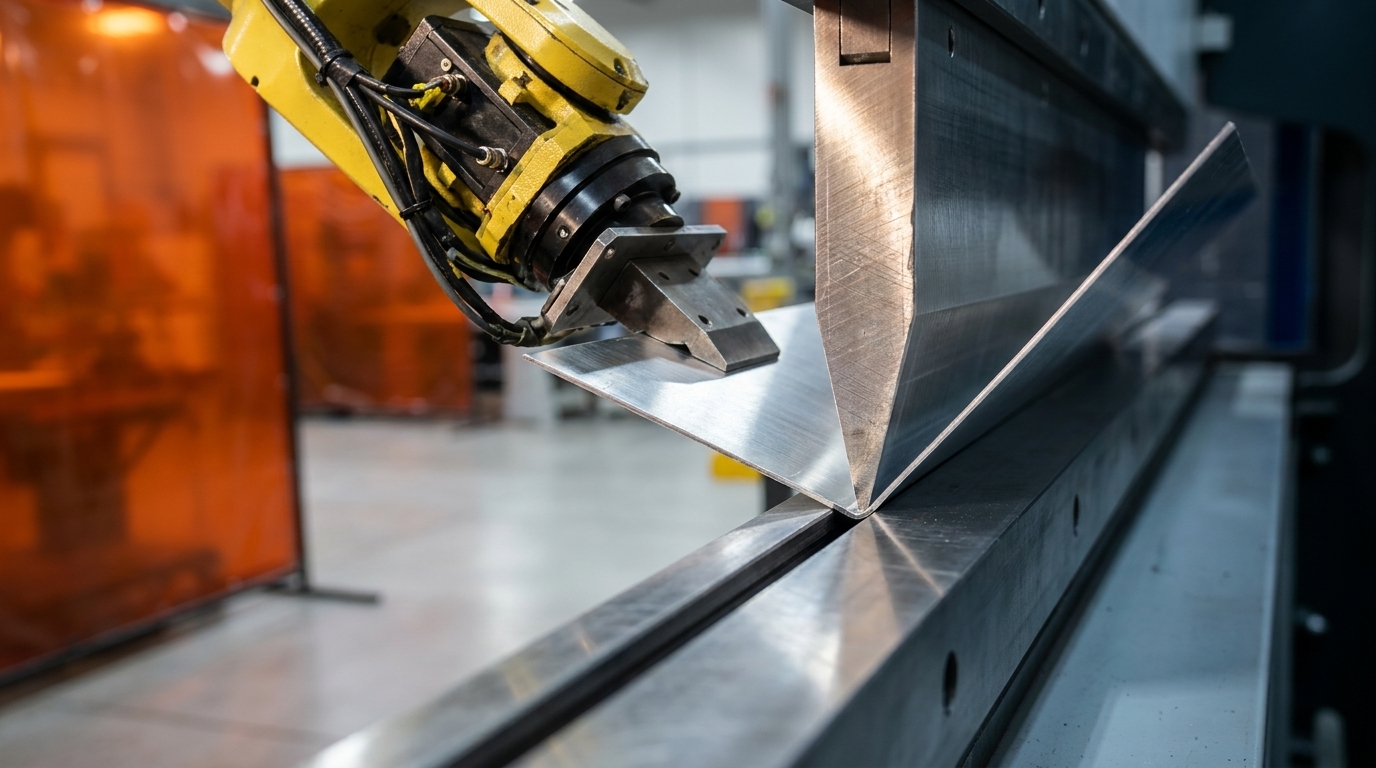
Bend sequence defines which features form first and how the blank moves at each step. Each bend changes the blank shape, shifts usable datums and creates new collision points for later operations.
General sequencing rules for common geometries follow.
- For U-channels, bend one side flange, rotate the part, then bend the opposite side while keeping the base stable.
- For box and pan forms, form internal or short return features first, then sidewalls, then closing bends.
- For parts with return flanges, simulate the punch approach path at each stage to find interference with previously bent flanges.
Deep channel geometries restrict tool access and back-gauge positioning. When channel depth requires it, the drawing should specify gooseneck punches. Quick-change clamping systems cut setup time and support high-mix production with frequent tool changes.
Setting Tolerances and Datums for Real Shop Conditions
Sheet metal parts experience springback, material thickness variation and tooling deflection. Tolerances that ignore these factors raise inspection cost and rejection rates without improving function.
ASME Y14.5-2018 is the authoritative U.S. standard for geometric dimensioning and tolerancing and should appear explicitly in the drawing title block. Datum reference frames should start from stable, machinable surfaces when possible. Angle allowances of one or two degrees are recommended for mating features on bent sheet metal parts, because springback variation makes tighter angular tolerances expensive to hold.
Machined-part tolerances should not appear on formed features. Flatness, angularity and position callouts on bent flanges must reflect the forming process as well as design intent.
Common Sheet Metal Design Mistakes That Trigger Rework
Frequent DFM violations in sheet metal programs often trace back to design decisions made without shop-floor input. The most costly issues include the following items.
- Holes placed inside the 2T + R zone that require post-bend drilling or part replacement.
- Non-standard material thicknesses that extend procurement lead time and complicate nesting.
- Missing bend relief at intersecting flanges that causes corner tears on first articles.
- Inconsistent bend radii across a part that require multiple die setups and increase cycle time.
- Hardware installed after painting or powder coating that damages the finish and requires rework.
- Over-toleranced drawings that specify machined-part precision on formed features and drive unnecessary inspection cost.
Parts with fewer bends usually run faster than parts with many bends because each bend needs a separate setup, repositioning and inspection step. Consolidating bends and simplifying geometry during design cuts cycle time and lowers the chance of sequencing errors by reducing the number of operations.
Aligning Sheet Metal DFM With ISO 9001 and AS9100
ISO 9001:2015 and AS9100D quality systems embed DFM rules into documented work instructions, first-article inspection records and change-control processes. Each rule in the checklist maps to a quality checkpoint. Bend radius minimums appear in material and tooling qualification records. Hole-to-bend distances are verified during first-article inspection. Tolerance callouts are reviewed against the drawing standard before production begins.
For aerospace, defense and medical device programs, full traceability from raw material to finished assembly is a regulatory requirement. AS9100D certification requires documented nonconformances, root-cause analysis and corrective actions with evidence. That structure catches DFM violations before they spread across a production run. ITAR registration adds another layer of access and documentation control for controlled-technology programs.
Fabcon holds ISO 9001:2015 and AS9100D certifications and is ITAR registered. Quality controls span fabrication, finishing and assembly under one roof to provide end-to-end traceability without vendor handoffs.
Reducing Program Risk With Early DFM Collaboration
DFM reviews completed before drawing release catch violations when they cost the least to fix. Once a part is cut and bent, geometry changes require new flat patterns, new tooling setups and new first-article inspections.
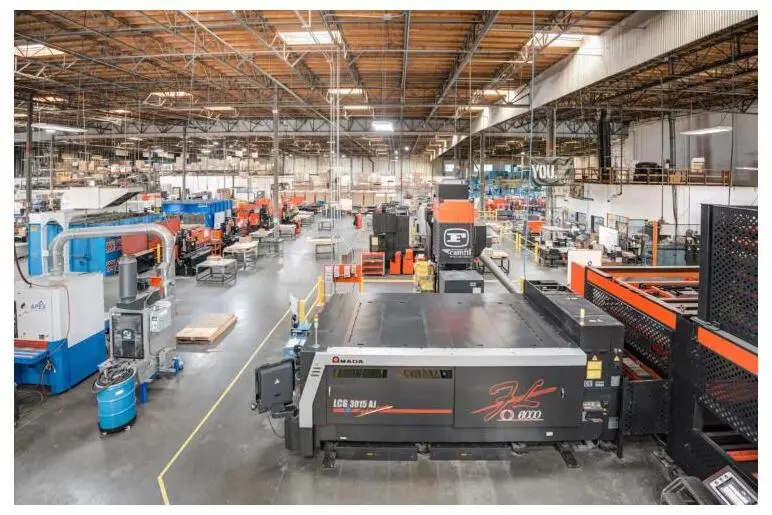
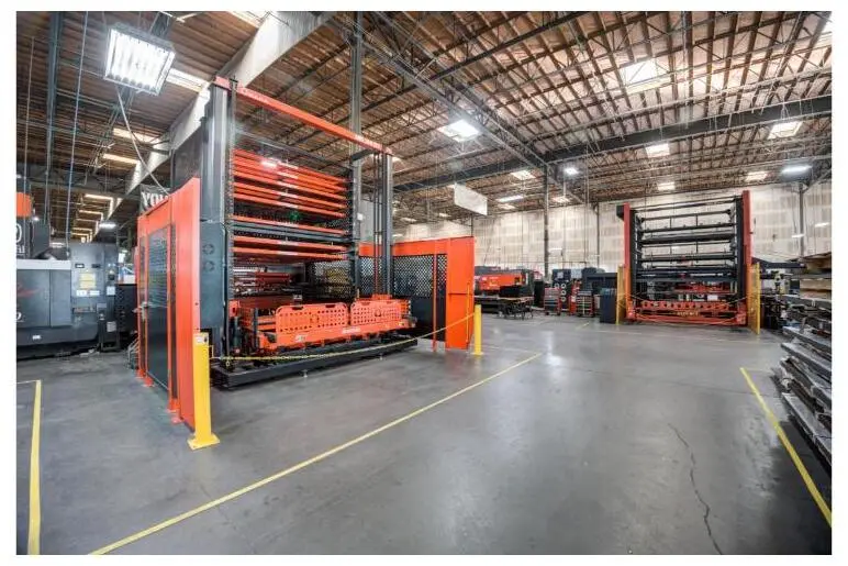
Consolidating laser cutting, press-brake bending, welding, hardware insertion and surface finishing under one roof cuts overall lead time because parts do not sit in queue between vendors or travel between facilities. A single partner with engineering, fabrication, finishing and light electromechanical assembly in one location removes vendor handoff delays and keeps quality accountability clear.
Fabcon’s engineering and quoting teams review drawings together before production. They evaluate bend sequences, flag hole-to-bend violations, confirm material availability in standard gauges and create manufacturing routers suited to the shop floor. Programs that enter production with DFM-reviewed drawings need fewer engineering change orders and produce more consistent first articles.
For data center enclosures, energy storage cabinets, aerospace structural assemblies and EV infrastructure components, that consistency forms the baseline expectation. Request a quote and connect with Fabcon’s engineering team at the start of the design cycle.

Frequently Asked Questions
What are the most common sheet metal design mistakes that cause rework?
The most common mistakes appear in the Common Sheet Metal Design Mistakes section above. Typical issues include hole placement violations, missing bend relief, non-standard material choices, inconsistent bend radii and unrealistic tolerances. Each violation is detectable during a DFM review before production begins, which removes the cost of scrapped first articles and engineering change orders.
What ISO standard applies to sheet metal design and fabrication?
ISO 9001:2015 is the primary quality management standard for sheet metal fabrication processes in the United States. For aerospace and defense programs, AS9100D adds requirements for traceability, nonconformance control and risk management. On the drawing side, ASME Y14.5-2018 is the authoritative U.S. standard for geometric dimensioning and tolerancing and should appear explicitly in the drawing title block so that fabricators and inspectors apply identical rules.
How should an engineering team evaluate a sheet metal fabrication partner?
An engineering team should evaluate a fabrication partner on four criteria. First, confirm that the partner holds relevant quality certifications, with ISO 9001:2015 as a baseline and AS9100D for aerospace and defense programs. Second, assess whether the partner includes DFM review in the quoting process instead of treating it as a separate engagement. Third, determine whether fabrication, finishing and assembly occur under one roof, because fragmented supply chains introduce handoff delays and dilute quality accountability. Fourth, confirm that the partner has experience with the alloys, gauges and tolerances required by the program. A partner that engages at the design stage and carries the program through production reduces total program risk more than a lower-cost vendor that builds only to print.
When should bend relief be added to a sheet metal part?
Bend relief is required wherever two bends intersect at a corner, such as at the junction of a side flange and an end flange on a box form. Without relief, forming stress concentrates at the corner and causes tearing. The relief notch must be wide enough to isolate the bending zone from the adjacent flat panel. Relief is also recommended when a hole or slot sits near a bend and cannot move far enough to meet the minimum hole-to-bend distance formula.
Does Fabcon support prototype and low-volume programs, or only high-volume production?
Fabcon supports programs from prototype through production using flexible manufacturing cells that adapt to changing volumes and mixed SKUs. The same DFM review, quality system and integrated finishing and assembly capabilities apply at prototype quantities and at production volumes. This continuity means that a design validated at prototype does not require requalification when volume increases, which reduces program risk and shortens time to market.
Conclusion: Turning Sheet Metal Rules Into Reliable Production
The rules in this checklist address common failure points in laser-cut and press-brake-formed sheet metal programs. Applied during design, they prevent quoting delays, first-article failures and rework loops that raise program cost and compress launch timelines.
Fabcon’s vertically integrated facilities combine engineering, precision fabrication, finishing and light electromechanical assembly under one roof, governed by ISO 9001:2015 and AS9100D quality systems. Early DFM collaboration with a single certified U.S. partner turns these rules into repeatable, compliant production from prototype through full-scale delivery. Request a quote and put the checklist to work on the next program.